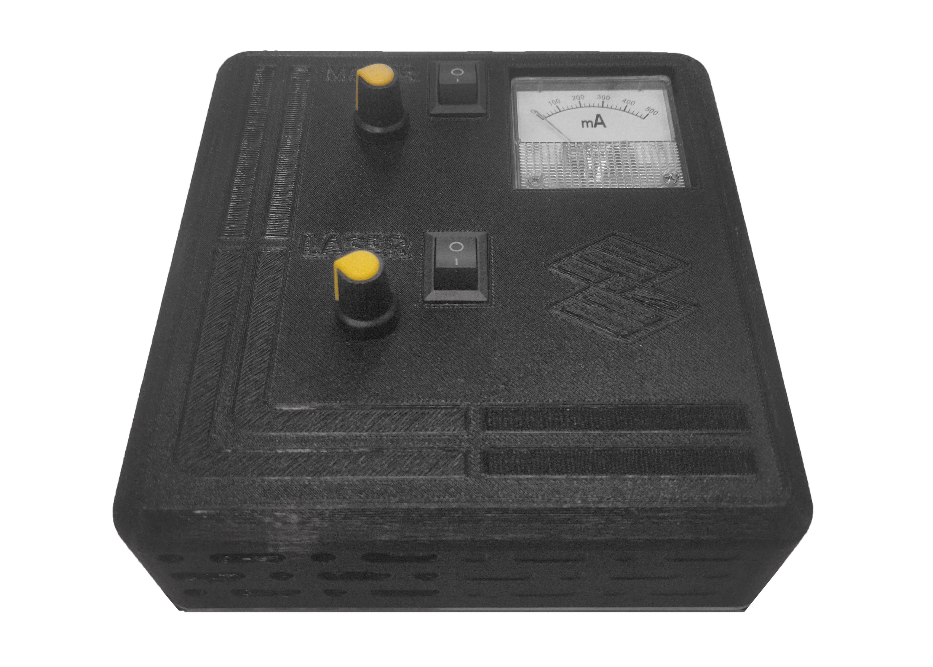
User Interface Module
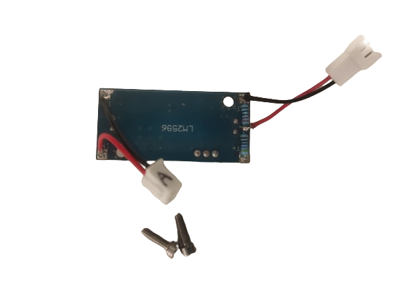
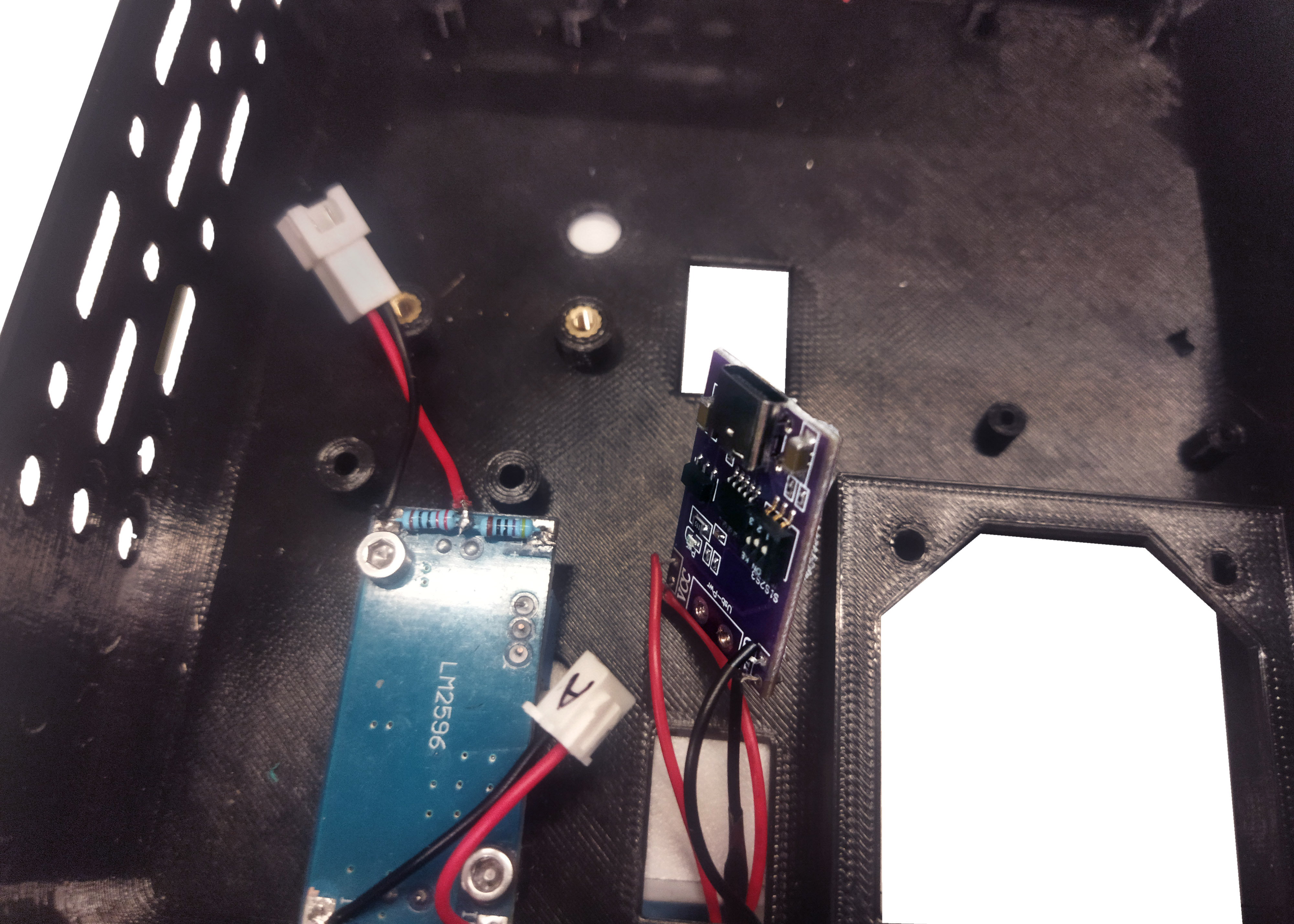
Step 1: LM2596
Position electronic card LM2596 such that the position of the potentiometer is correct, according to the perforation of the panel. Screw using M3 allen key and 2 M3X12mm bolts.
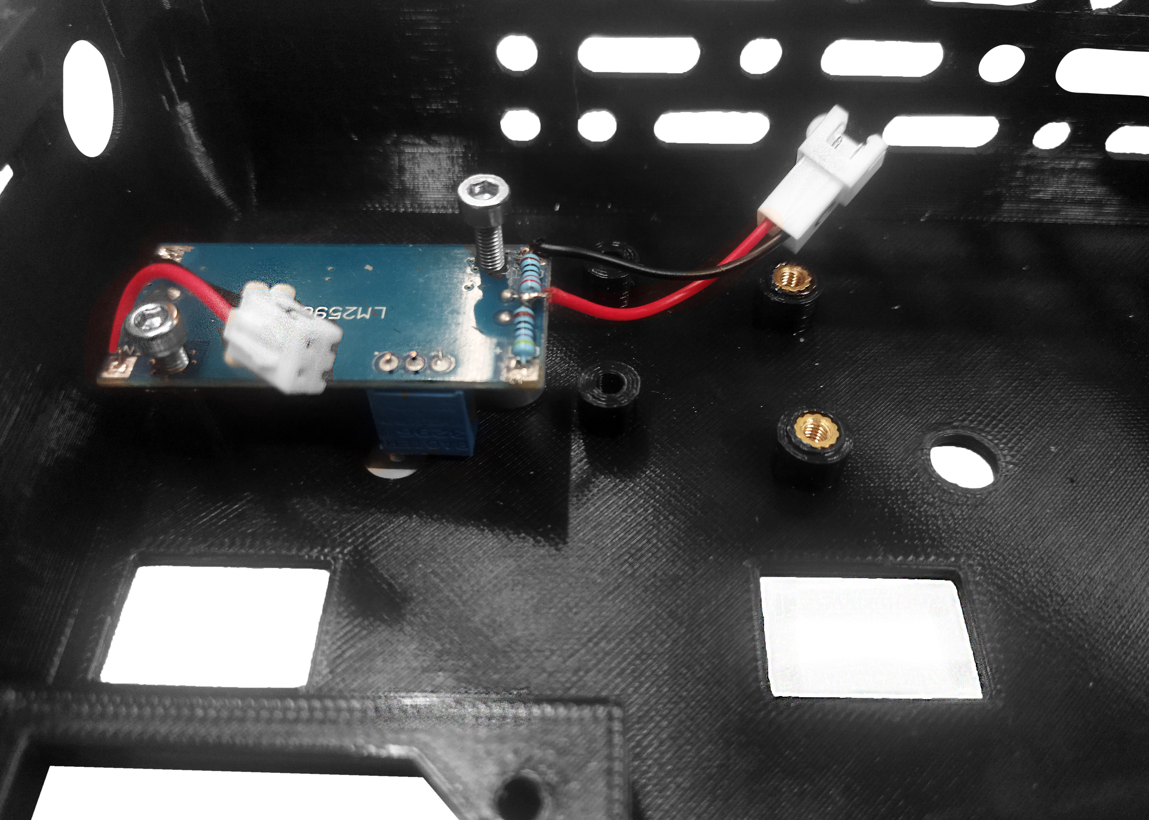
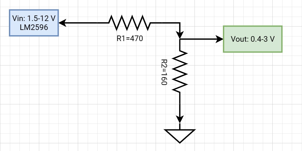
This electronic card has a voltage divider soldered on so that it can deliver a regulated voltage between 0.4-3V. The purpose of this component is to facilitate the optional extension of the module by adding a micro motor to induce fiber vibration and homogenize the laser speckle noise. This is not required for basic laser light output.
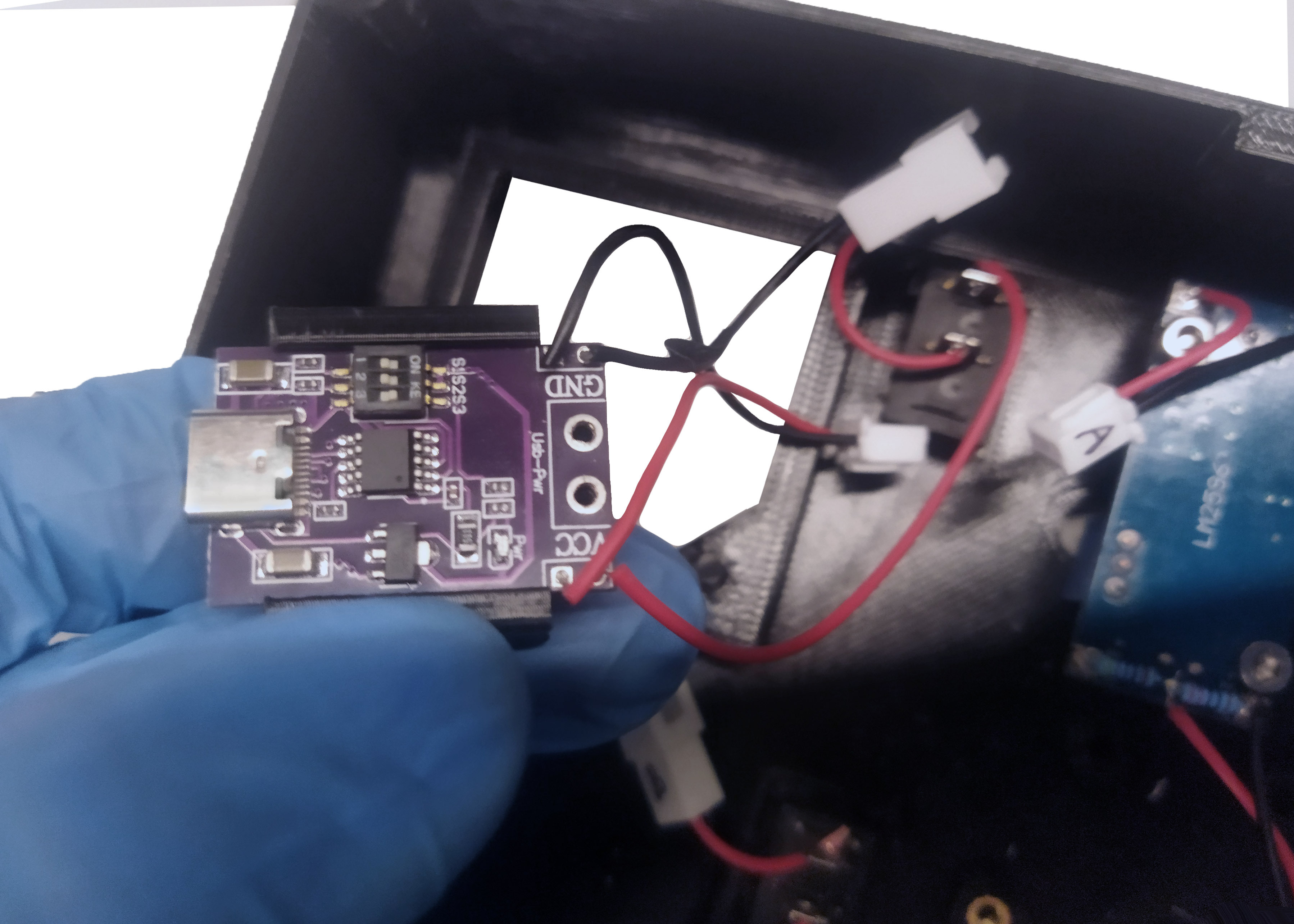
Step 2: Power supply module
The laser system is powered by a USB powered 12V interface module sold as “Fast charge decoy trigger PD/QC/AFC” module.
Set switches S1, S2, S3 to positions 1, 0, 1 so that the module supplies a voltage of 12V.
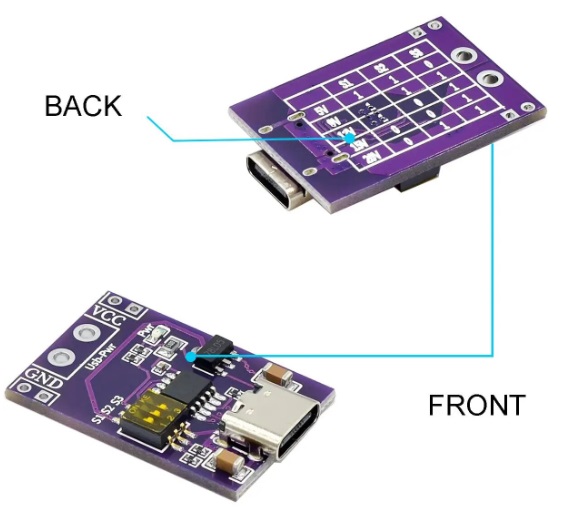
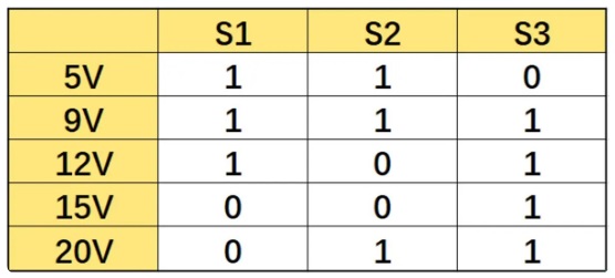
The configuration of the switches may vary from the one indicated. To verify please look at the combinations detailed on the back of the electronic card.
Step 3: Switches
Insert electronic card with previously soldered switch, through the hole for the motor switch located in the panel. This switch activates the optional vibrator micromotor to decrease the speckle present in the laser light beam.
If you want to use the vibrating micromotor, you must attach it to the holder and this at the same time to the laser's optical fiber to transfer the vibrations.
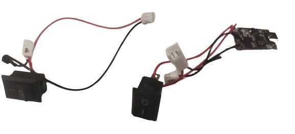
Insert the second switch through the laser hole and press to secure to the panel. This switch activates the laser.
For soldering the switches please consider the following electrical connection diagram
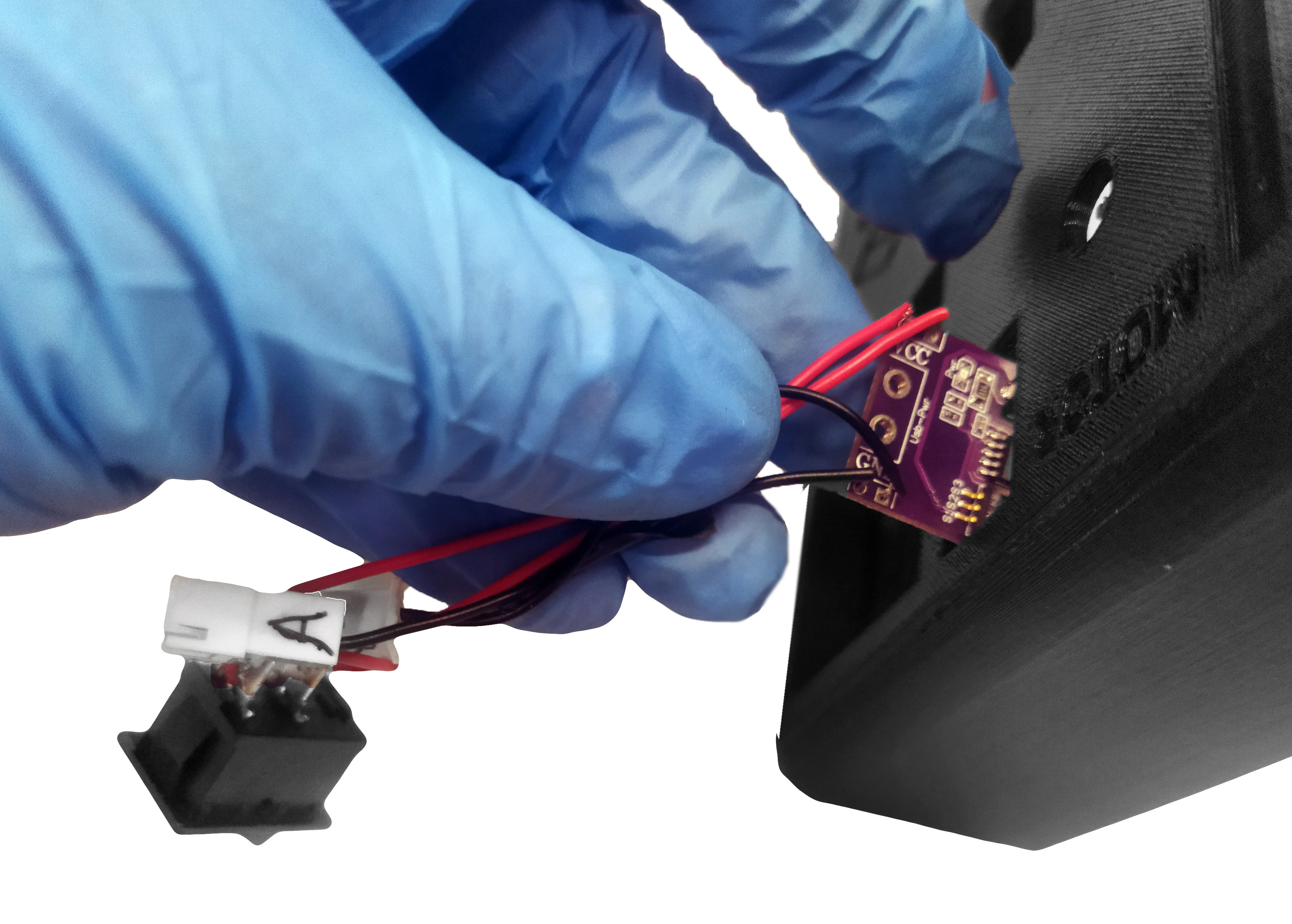
Step 4: Purple electronic board assembly
Align the purple electronic board with the plastic adapter as shown below.
Screw two M2x10mm bolts to fix the electronic card.
It is recommended to place bolts on separator to avoid short circuit.
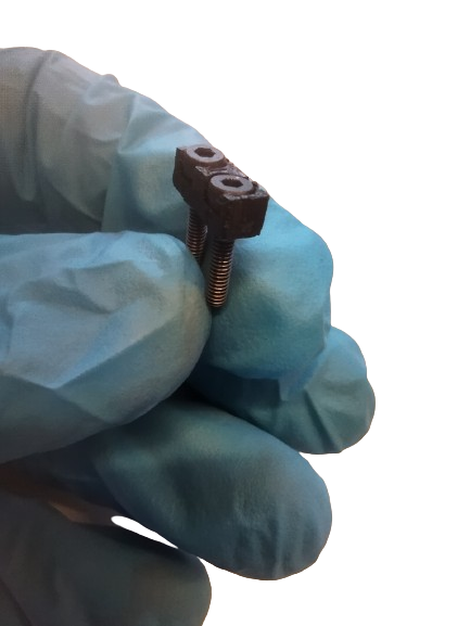
Insert two M3x10mm nuts and then fix to the panel.
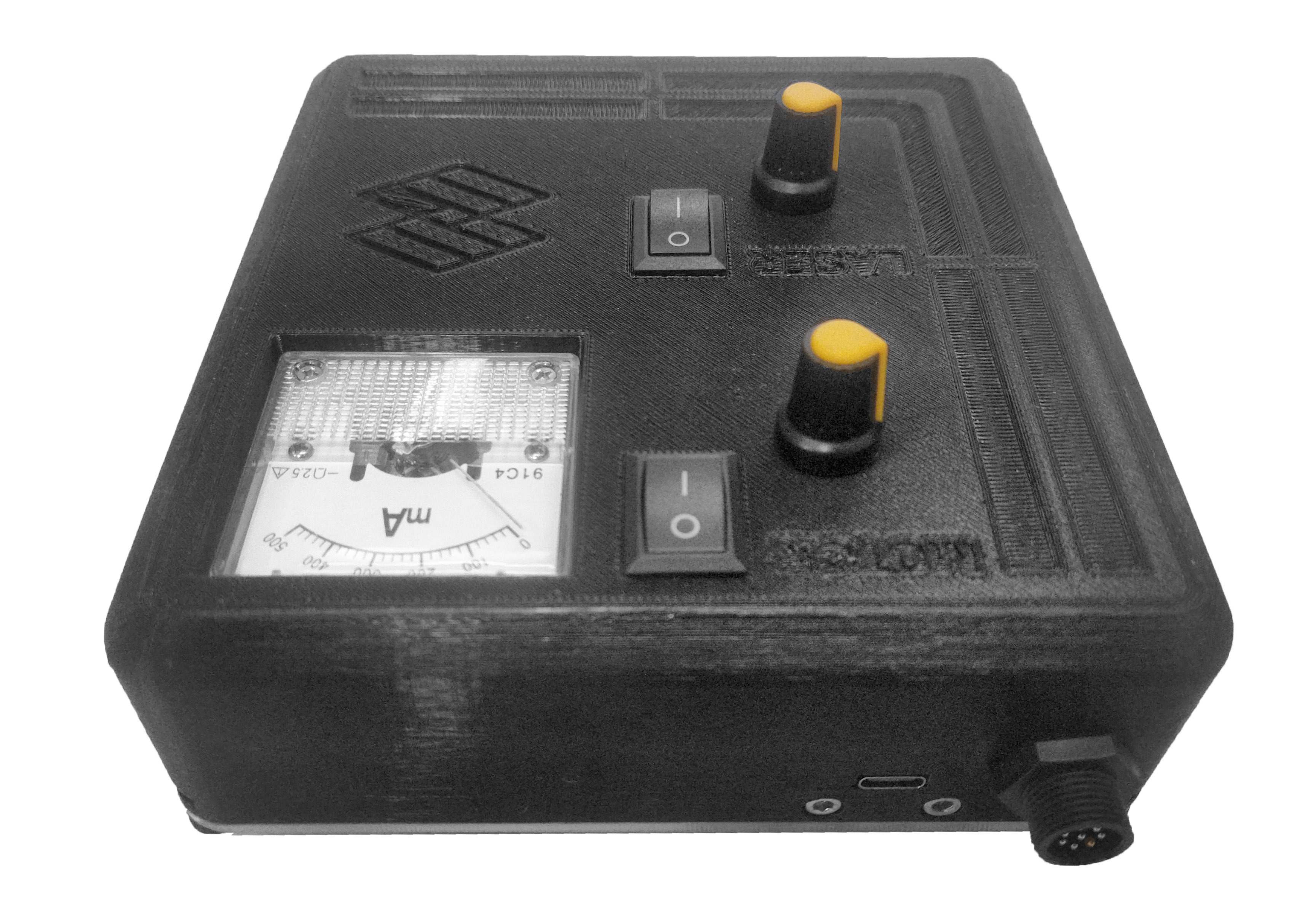
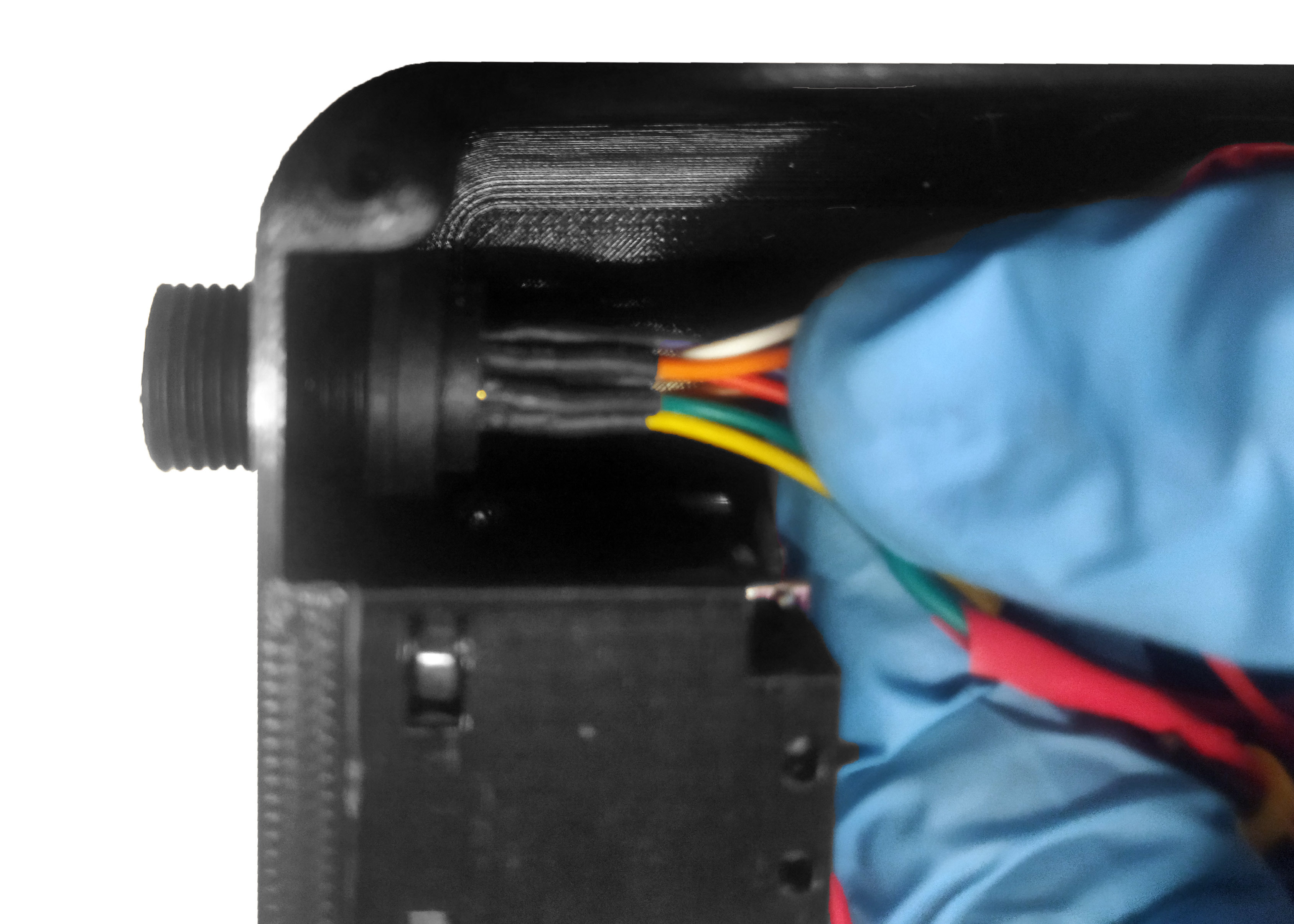
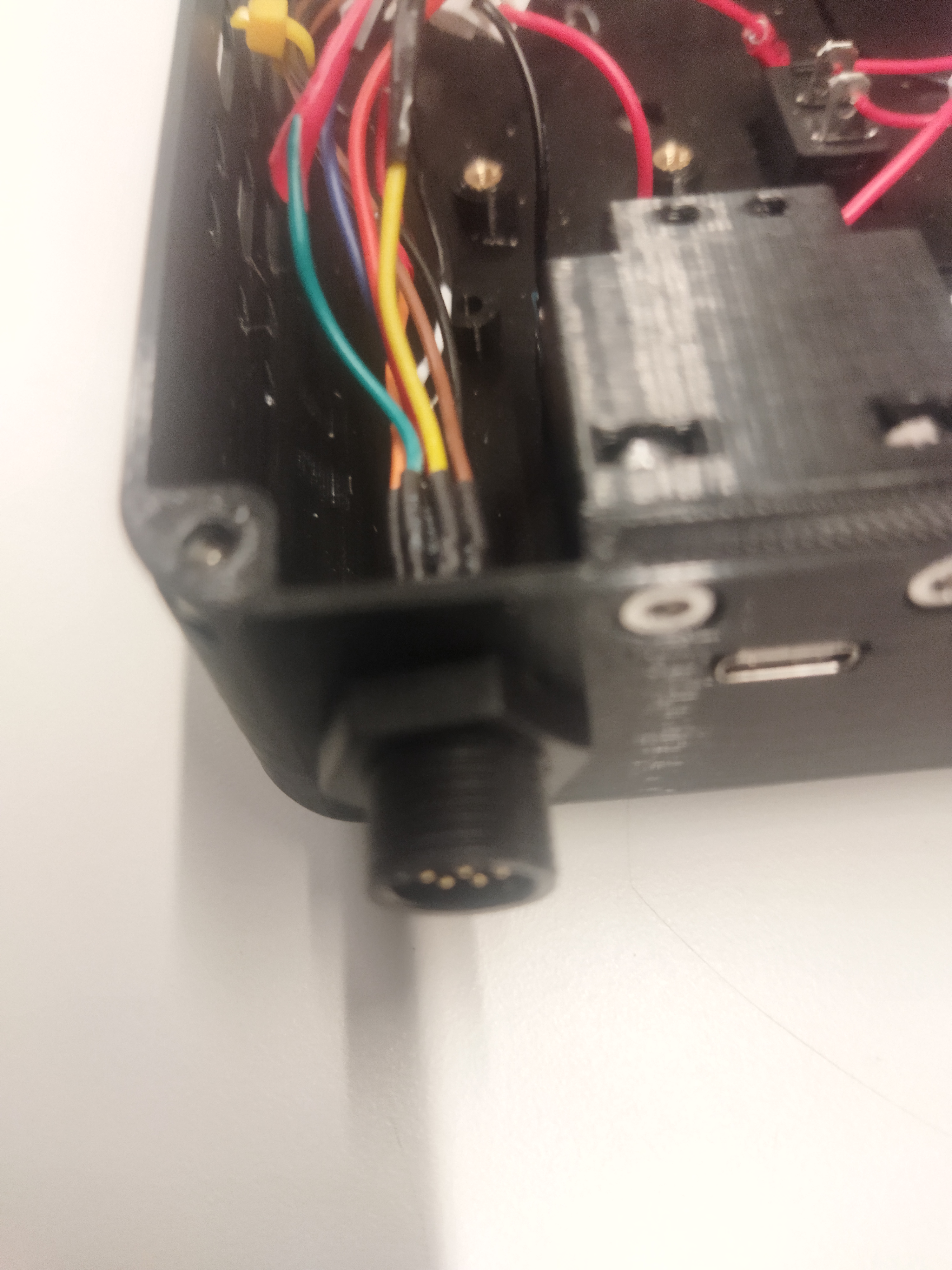
Step 5: M12 adapter cable fixing
Insert M12 connector from the inside of the panel in its respective perforation. Then tighten the M12 nut.
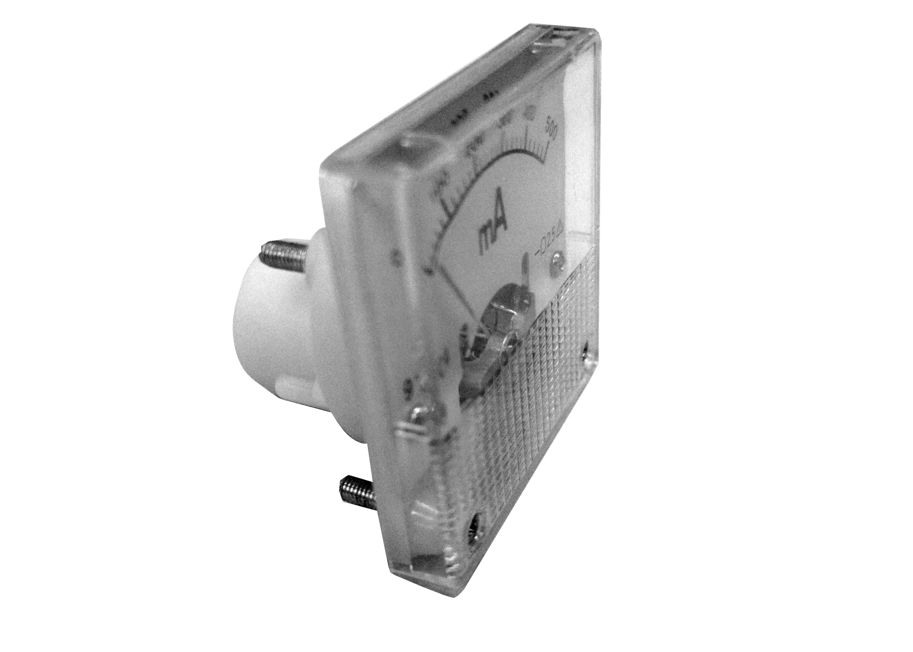
Step 6: Ammeter
Insert and press the ammeter in the panel. Fix the ammeter with M3 nuts.
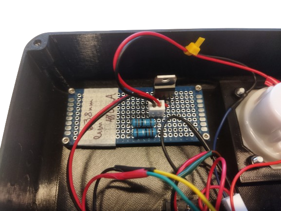
Step 7: Fixing current limiting circuit
Position and fix the 3x7cm electronic card on panel using the 4 M2x10 screws included. Respect guidance according to the following images.
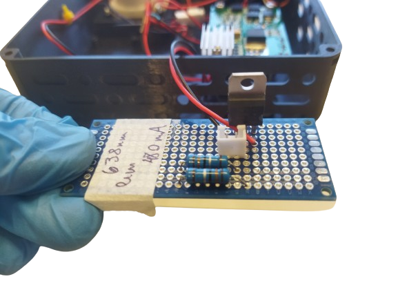
The electronic card is only included in kits whose laser has a wavelength of 405 nm or 638 nm. For more information go to the following link Current Limiting Circuit
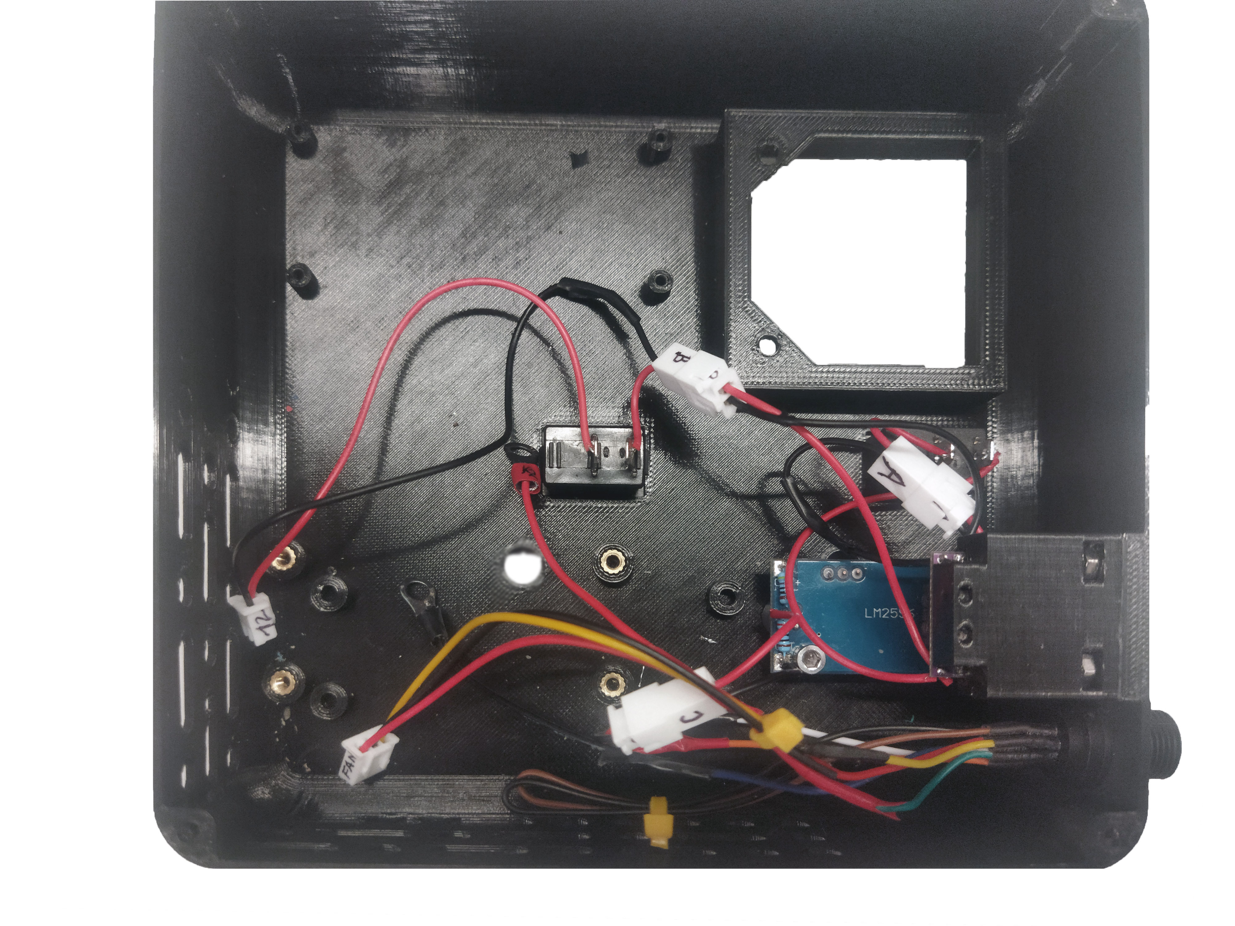
Step 8: Cable connection
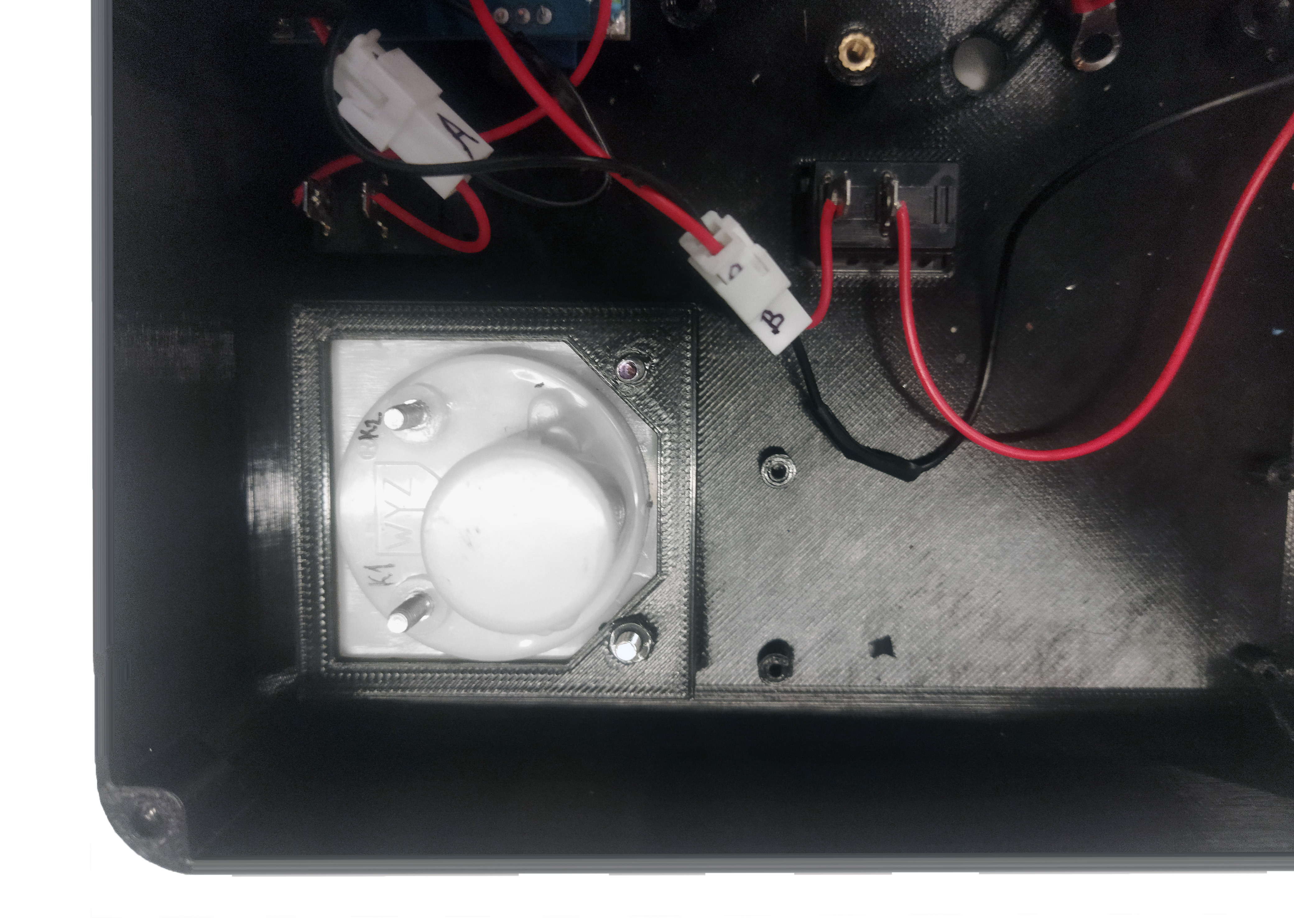
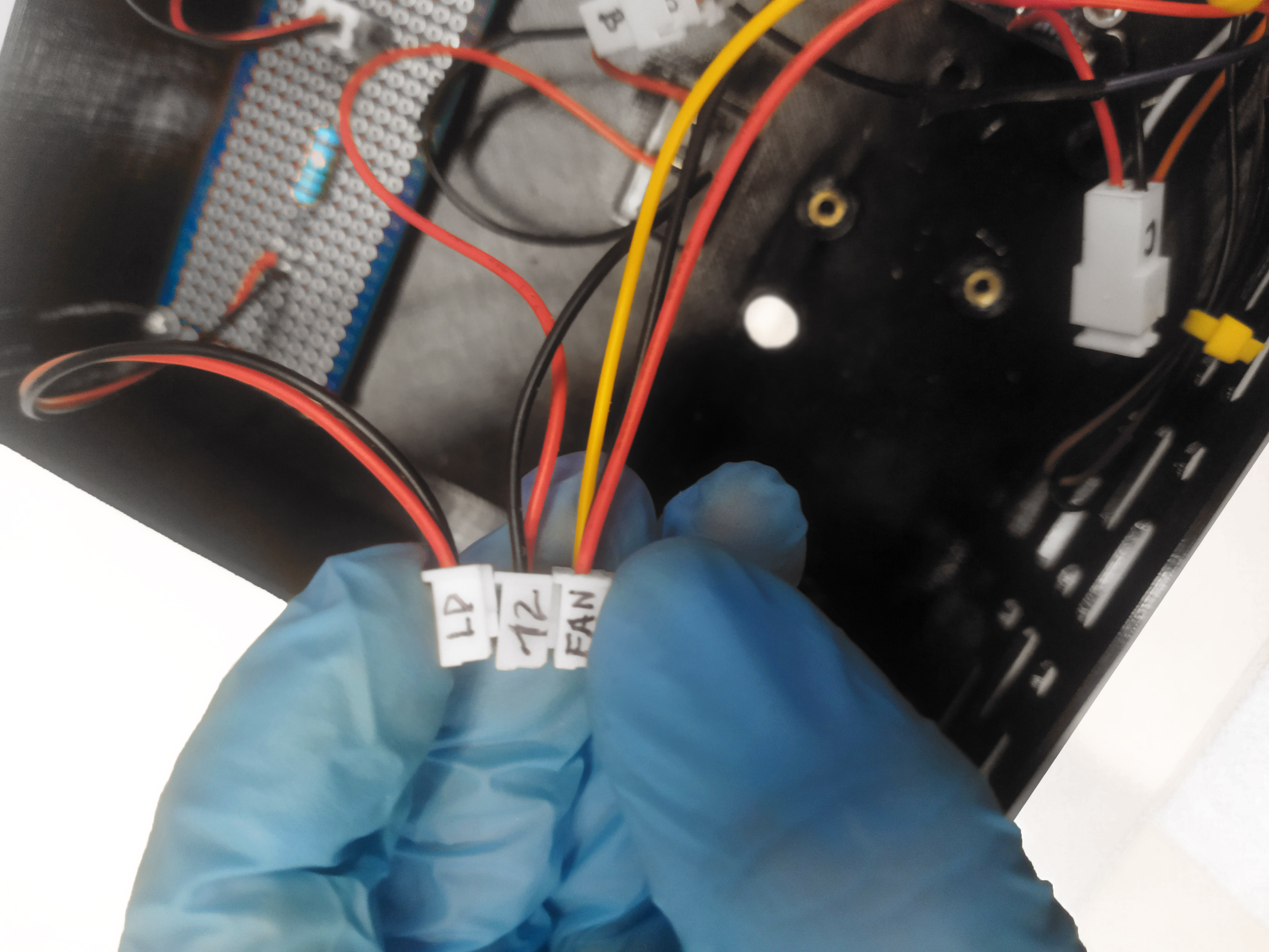
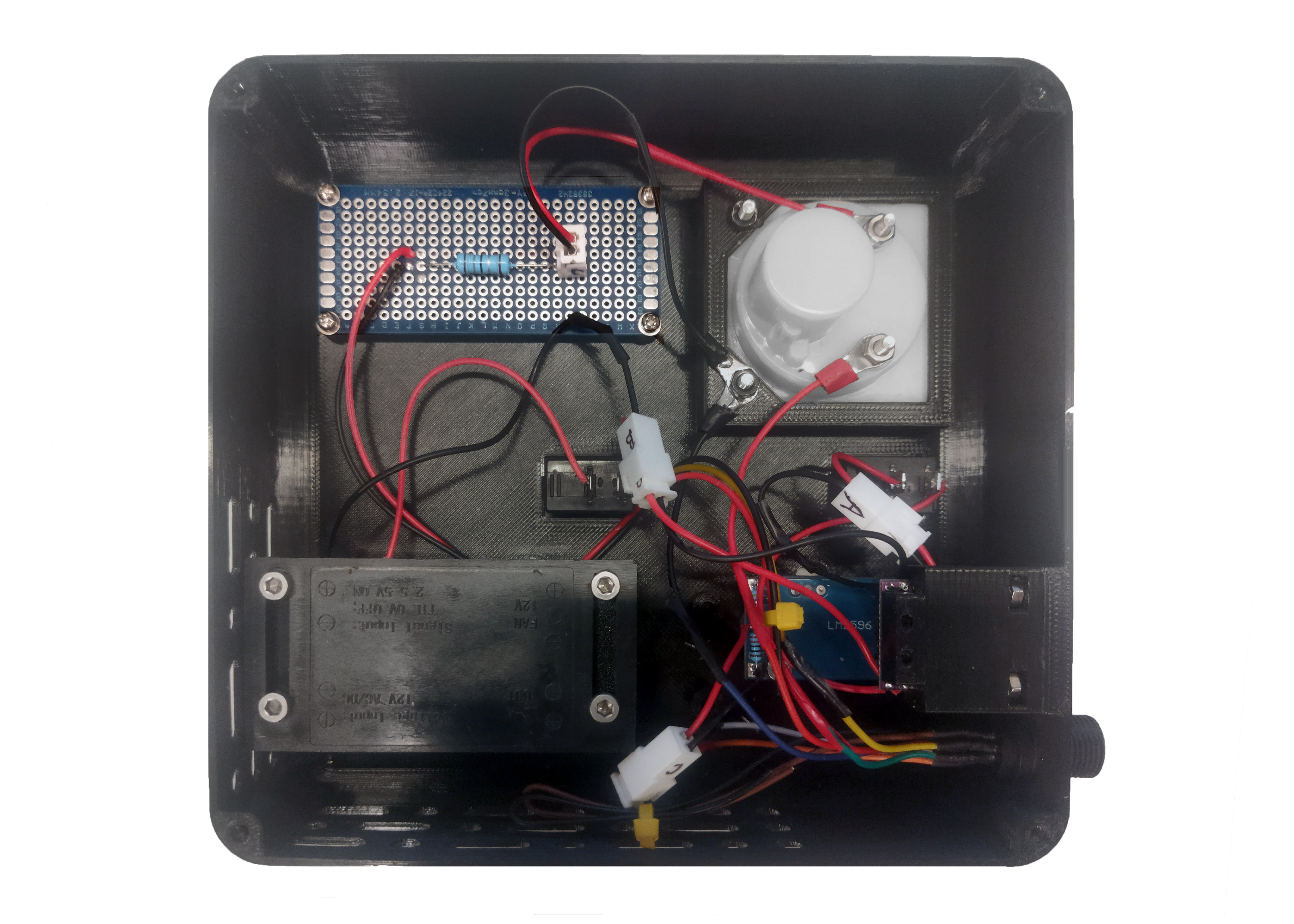
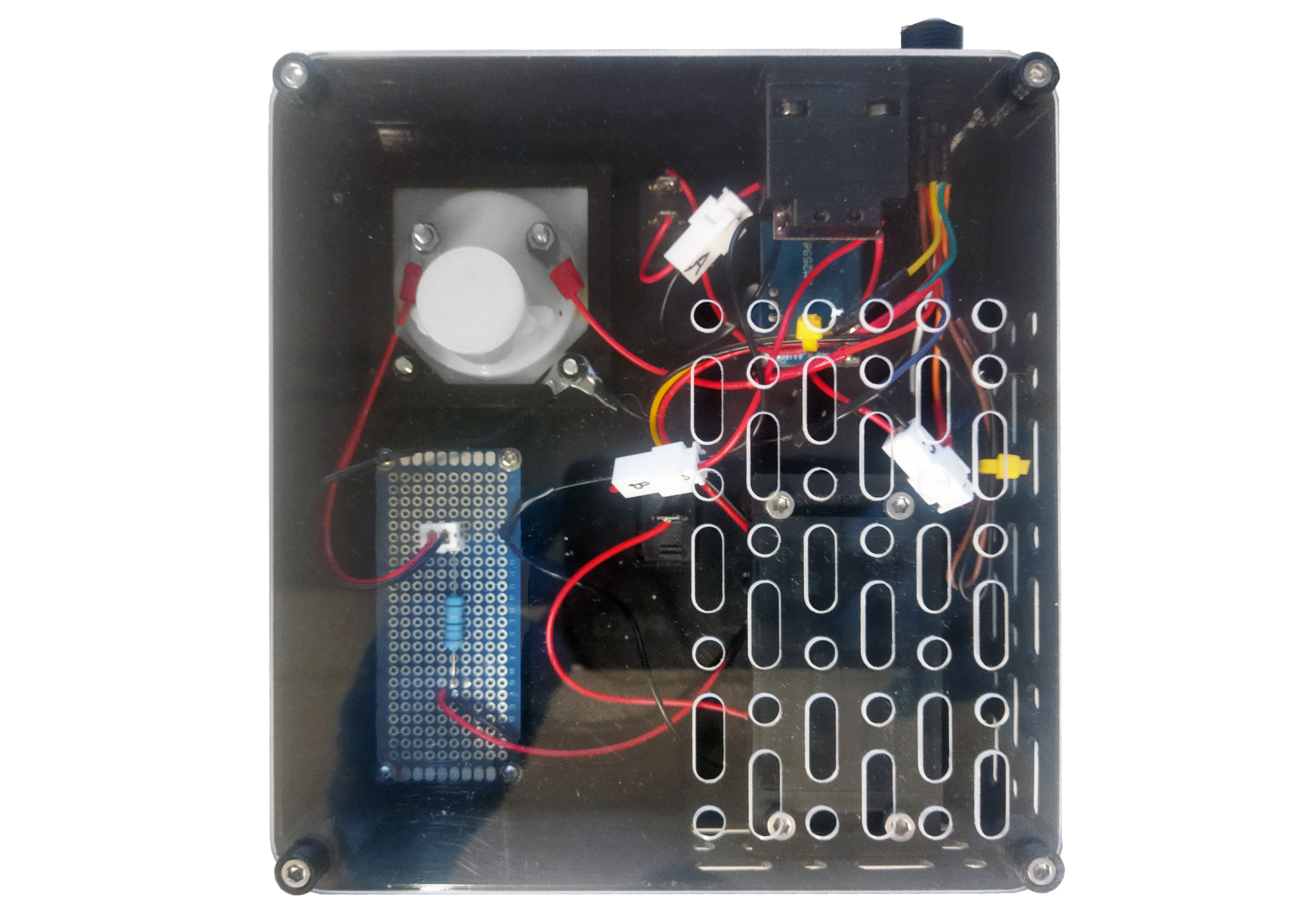
Connect wires A, B, C in the same letter as appropriate. Connect terminals K1 and K2 in the positions indicated on the ammeter. To connect the RV2 terminals, use M3 nuts. Consider the electrical connection diagram detailed below:
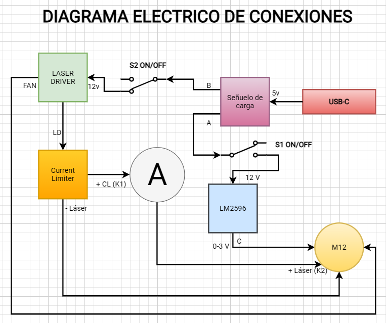
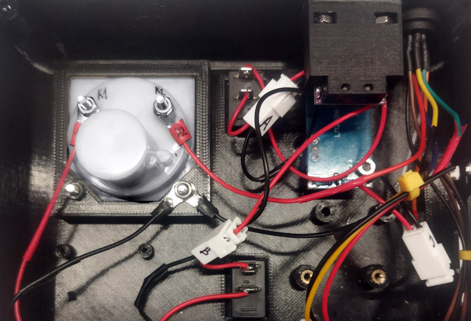
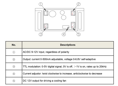
Connect 12V and FAN cables to the "laser driver" card in ports 1 and 5; 12V power and fan respectively.
For connecting port 2 (LD) of the "laser driver", which corresponds to the output of the adjustable current source that powers the laser. Consider the following:
If the current limiting circuit is included: Connect port 2 of the laser driver directly to the card with the current limiting circuit. And subsequently from the output port of the current limiting circuit, connect the + pin to the ammeter (K1) and the - pin to the laser anode, as illustrated in the electrical diagram described above.
If current limiting circuit is not included: Connect pin + of the LD port of the "laser driver" directly to the ammeter (K1), and pin - to the laser anode.
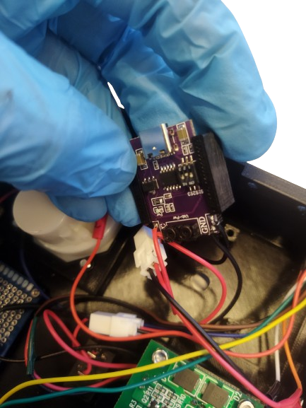
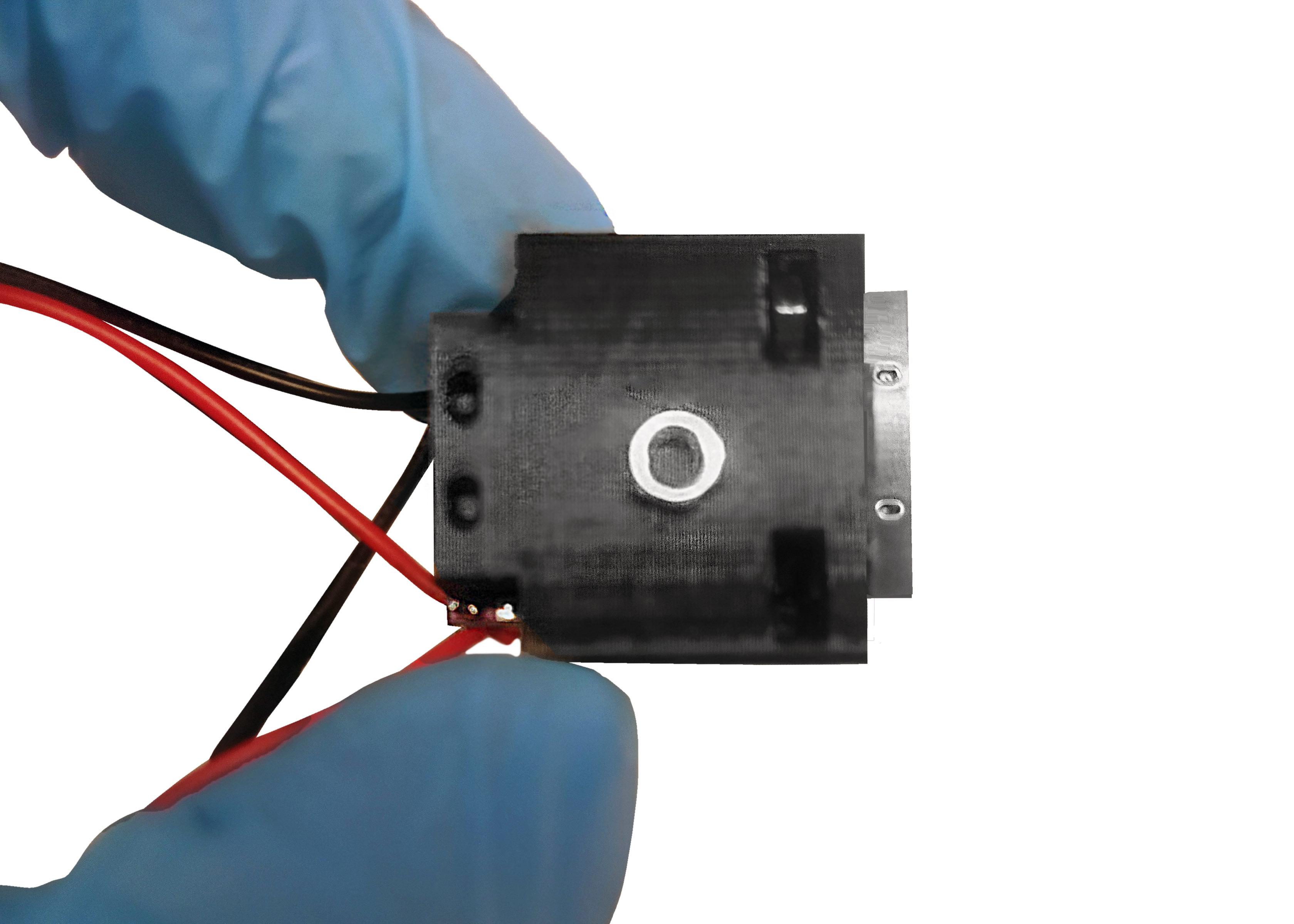
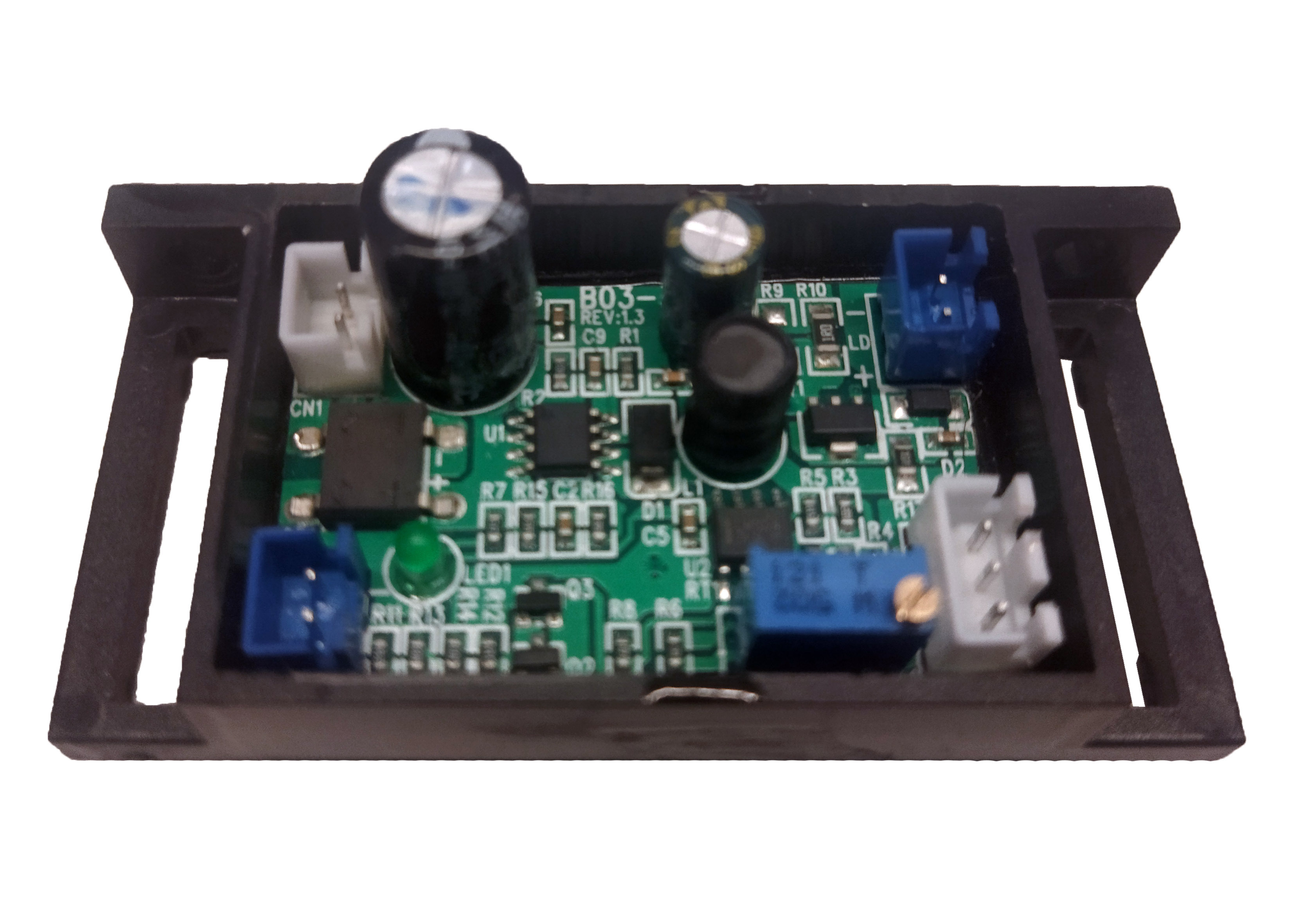
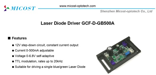
Below are photographs of the "laser driver" included in the kit, along with a representative image of the connections. The technical specifications of the "laser driver" can be found in the following link Micost driver 500mA.
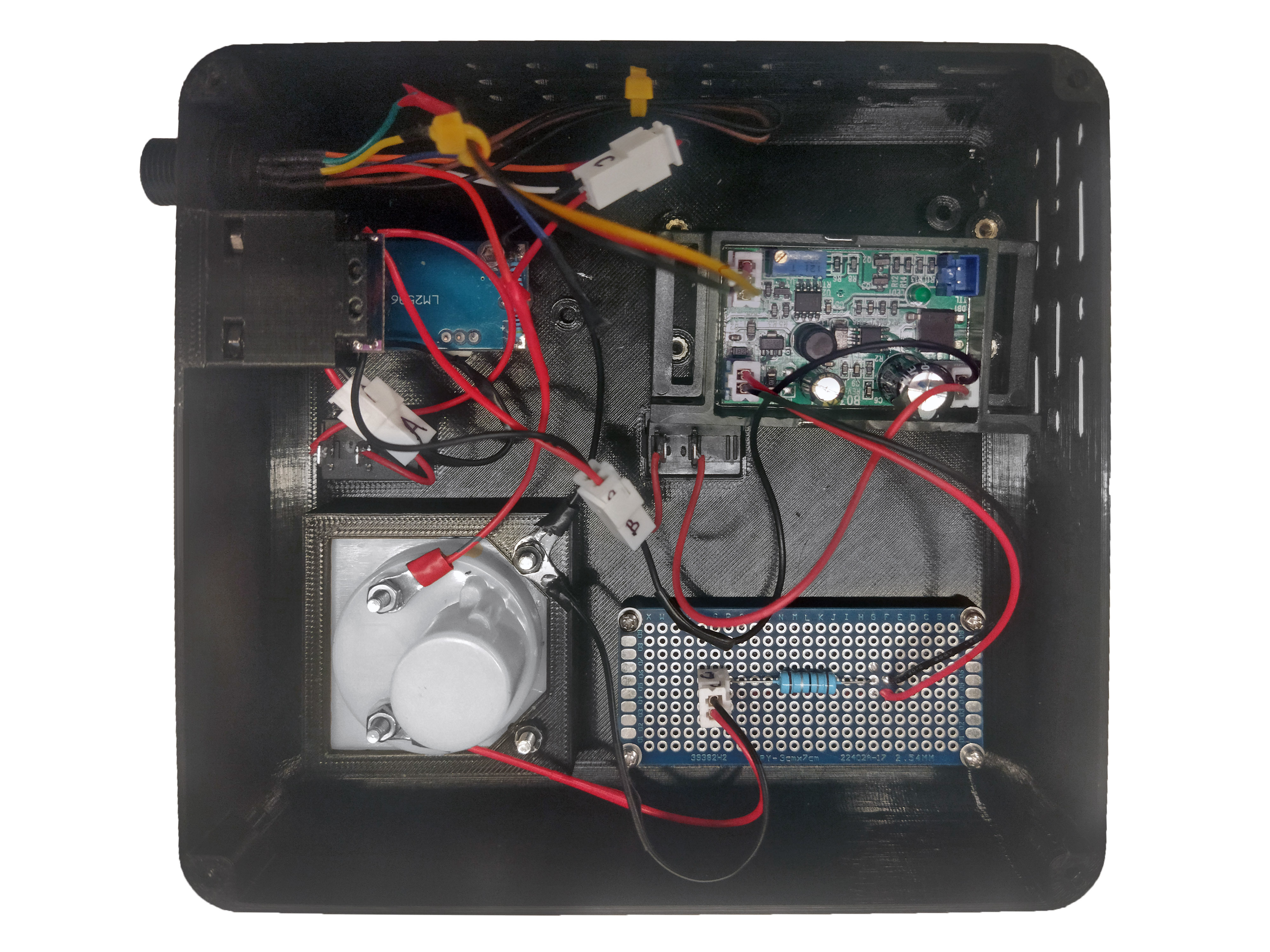
The cables used correspond to the XH54 model with 2 male/female pins, but another model that is available can be used.
Step 9: Fixing the laser driver
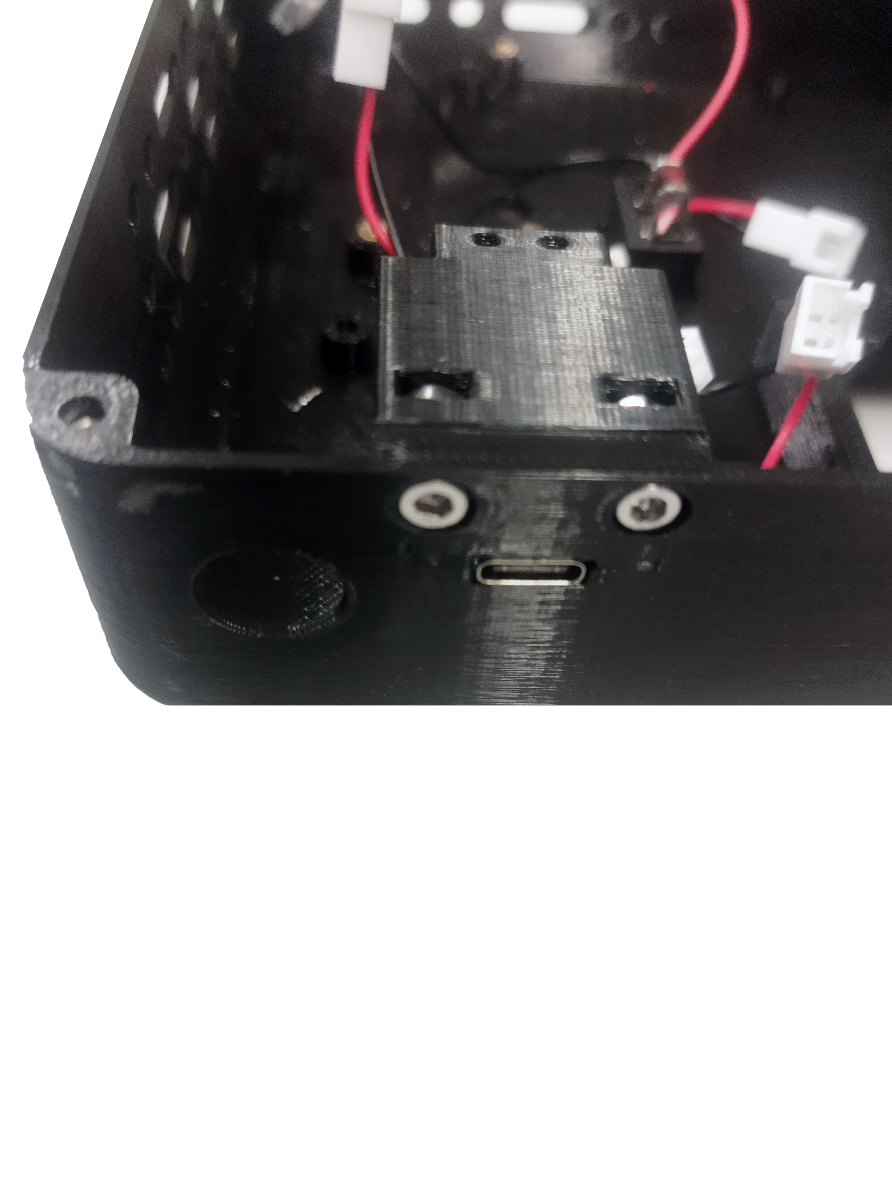
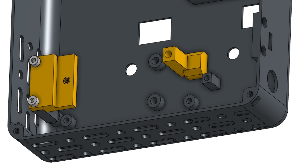
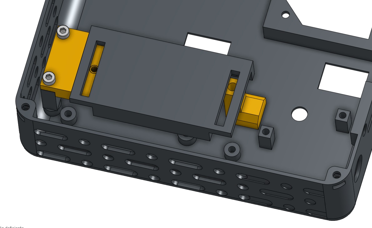
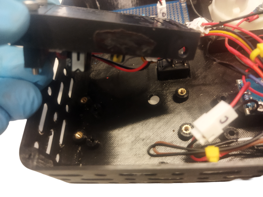
Flip the laser driver card, orienting it so that the potentiometer is well positioned. Join and bolt spacers S1 and S2 using M3X25 bolts directly to panel according to the photograph. Position and press separator S3 to panel. Finally, bolt the "laser driver" with 2 M3x6 bolts to the spacers.
For a kit that includes a 638nm laser, position and press spacers S4 and S5, and then screw on the 4A laser driver. The technical specifications of the "4A laser driver" can be found in the following link Micost driver 4A.
Warning
For the position of the potentiometer to be correctly adjusted, you will probably have to redesign some dimensions of the separators S1, S2, S3 or S4 and S5. The above depend on the final position of the potentiometer in the electronic card (laser driver) that will use. For more information go to the following link separators
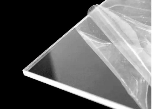
Step 10: Acrylic Protective Sheets
Remove protective sheets from the acrylic on both sides
Step 11: Acrylic part assembly
- Position 4 M3 nuts as shown in the following image.
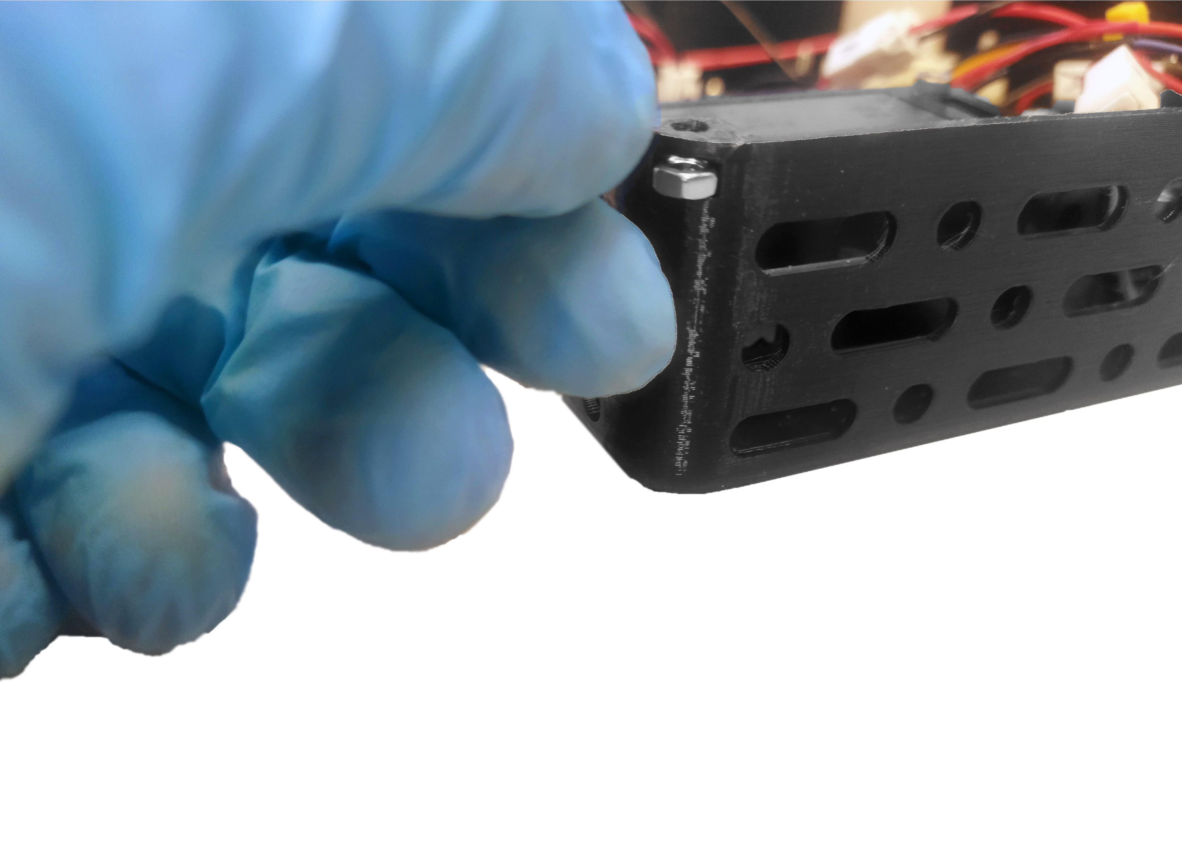
- Orient acrylic cap as shown in the following image.
- Fit spacers to 4 M3x10 bolts, then tighten.
- Paste non-slip rubber on each bolt.
Step 12: Knob assembly
Position and press knob 1 in motor hole and knob 2 in laser hole of panel. Later press knobs to improve grip.
Below is a photo of the fully assembled laser module.