Assemble the illumination
Tools
- 1 #1 pozidrive screwdriver
- 1 2.5mm Ball-end Allen key
- 1 Crimper
- 1 Needle-nose plier
- 1 Precision wire cutter
- 1 Soldering iron
Consumables
Electronic Components
- 1 2 pin Du Pont connector female housing
- 1 30x30x10mm Heat sink
- 2 Conductor Flexible Cables
- 1 Double-sided self adhesive tape
- 1 Double-sided thermal tape
- 1 High-power star LED
- 2 Male Crimp Pin
Mechanical Components
Optical Components
Printed Parts
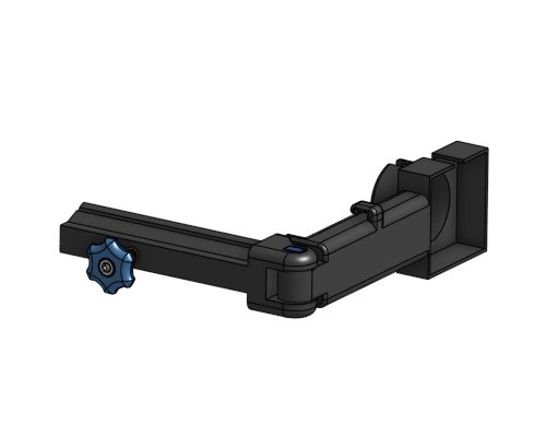
In this section, we are assembling the strobe illuminator. This mounts the high-power LED and condenser lens above the sample so the microscope can image the transmitted light.
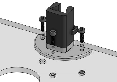
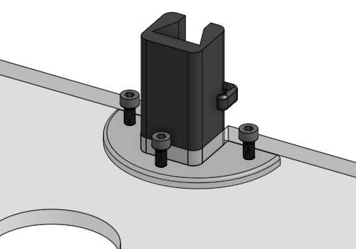
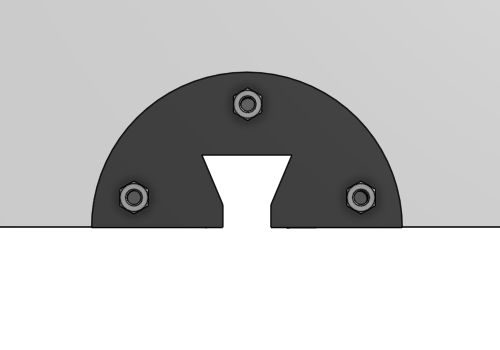
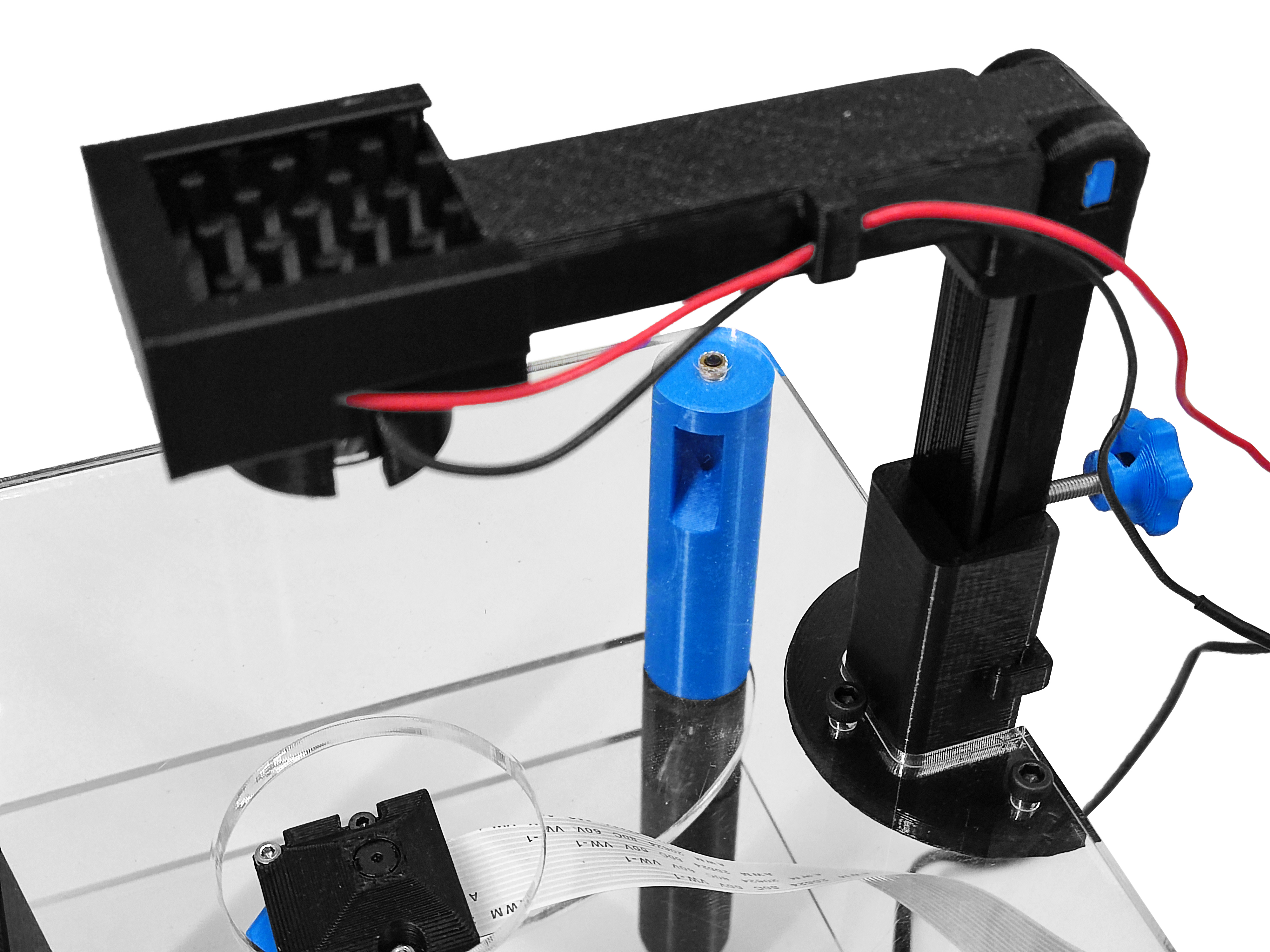
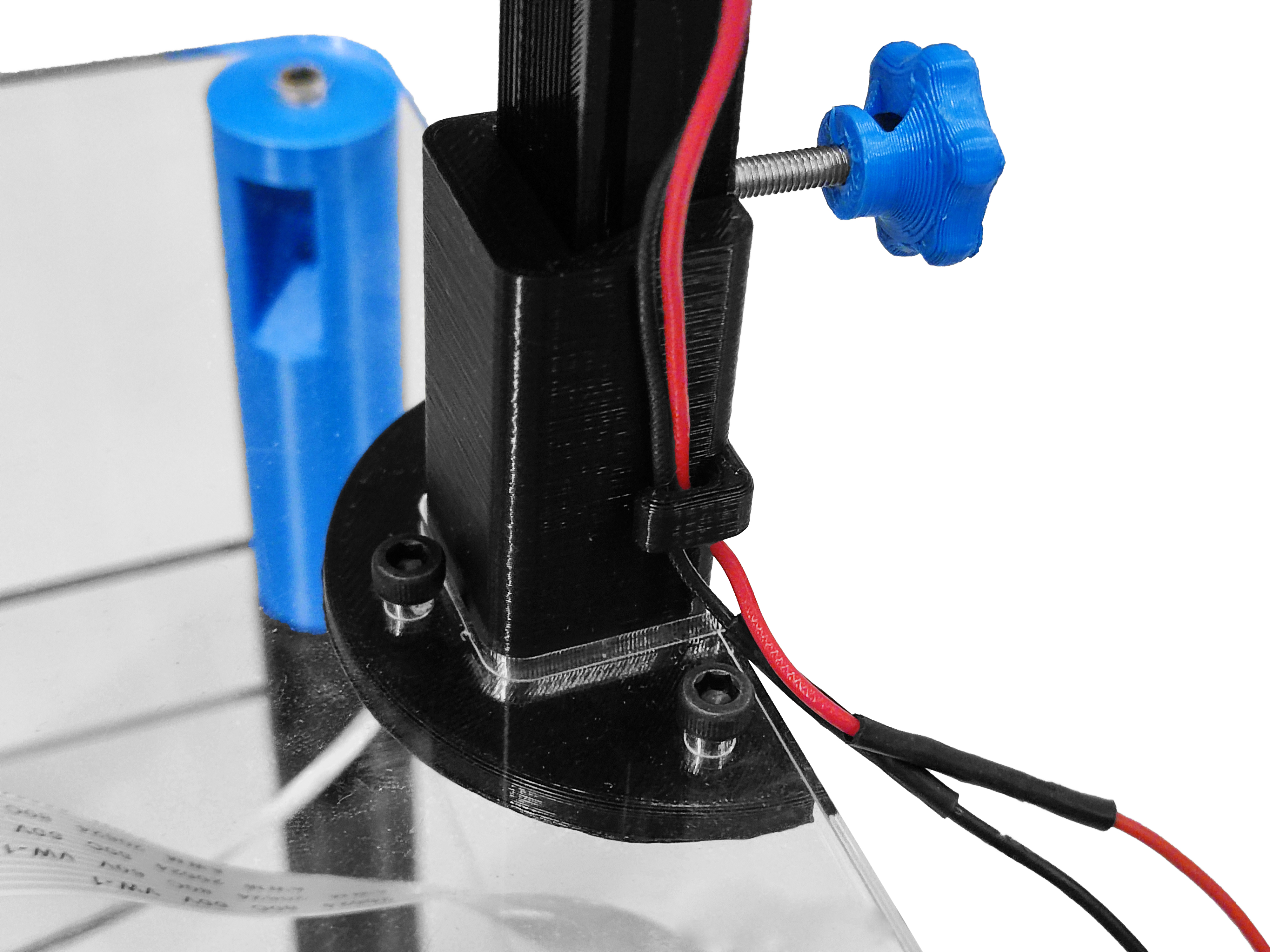
Step 1: Mount the base
- Place the illuminator base onto the top plate in opposite orientation to the focusing actuator.
- Secure in place with three M3x10mm screws and three M3 nuts (using a 2.5mm Ball-end Allen key)
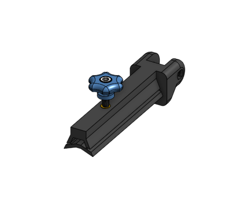
Step 2: Assemble the slider
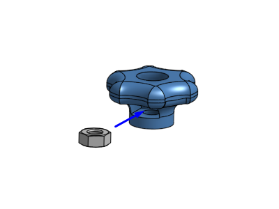
2.1) illuminator thumbscrew
- Push a M3 nut into the slot in the illuminator thumbscrew.
- Screw a M3x20mm pozi pan head screw into the thumbscrew. Use a #1 pozidrive screwdriver.
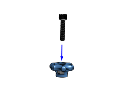

Be sure to properly clean the nut and screw holes before using them, if not it might break.
If the screw don´t go fully inside, you can do it with a plier and a screwdriver.
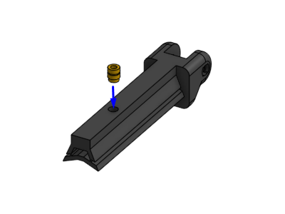
2.2) Illuminator slider:
- Positionate a heat insert in the round hole of the illuminator slider
- Apply heat to the insert (using a soldering iron) and use gentle force to push it into position as decribed in the guide to use heat inserts.
- Screw the thumbscrew assembly into the heat insert in the illuminator slider.
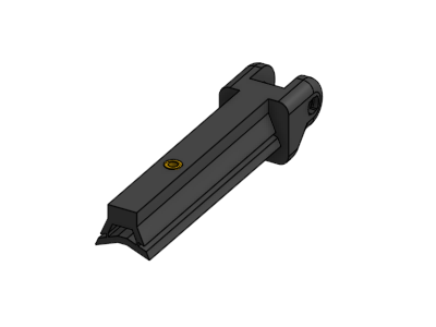
Warning
To ensure the slider works properly, it is necesary for the thinner section of the illuminator slider to break. This can be done using a plier.
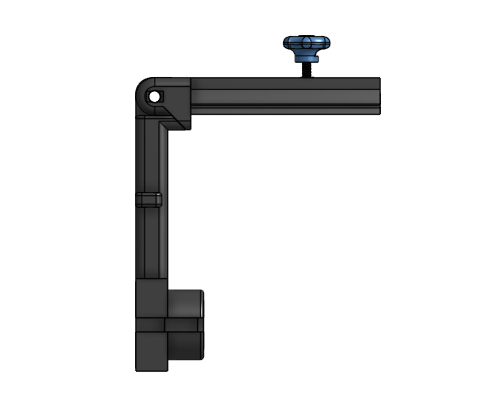
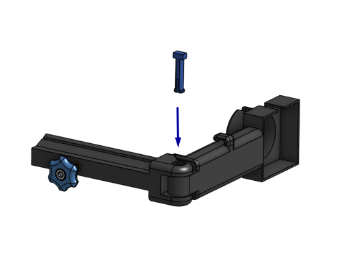
Step 3: Mount the light holder
- Put the illumination slider together with illumination arm, and align the holes.
- Use a hinge pin to connect them. Insert it into the rectagular side of the slider.
- It should take a little bit of force to push it through the holes. A needle-nose plier can be useful.
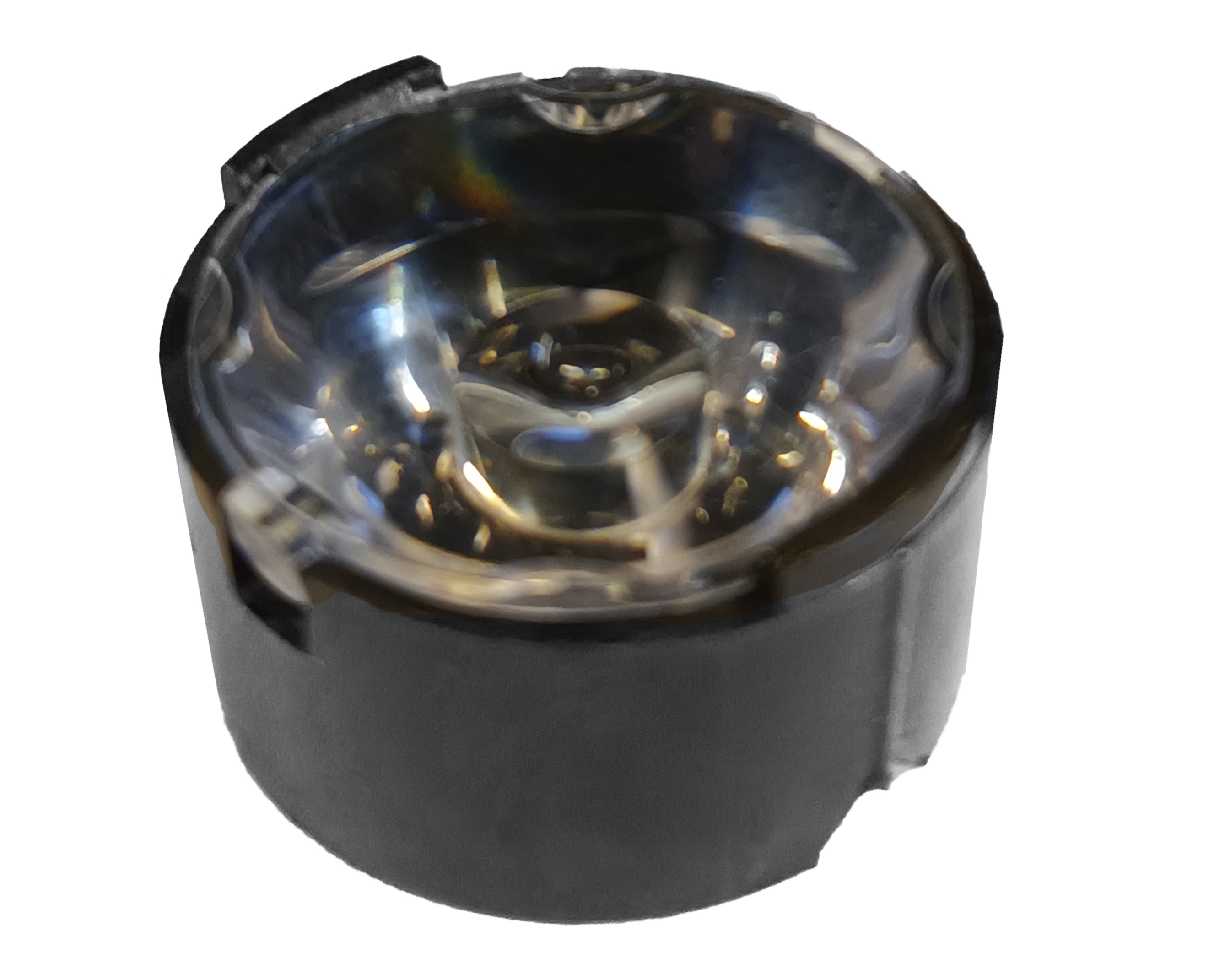
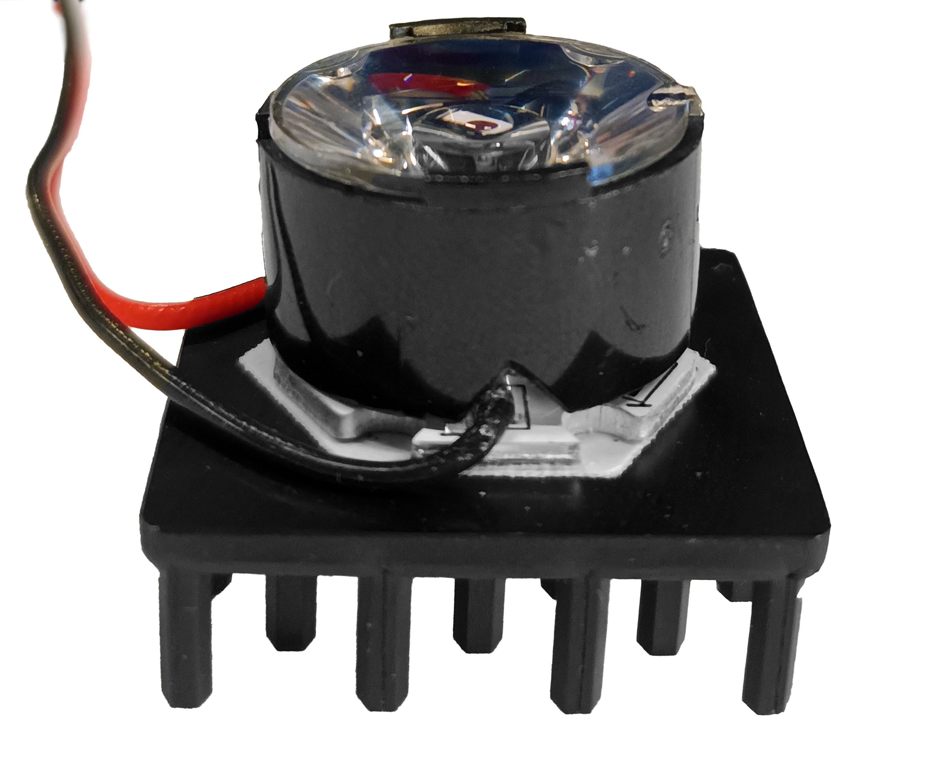
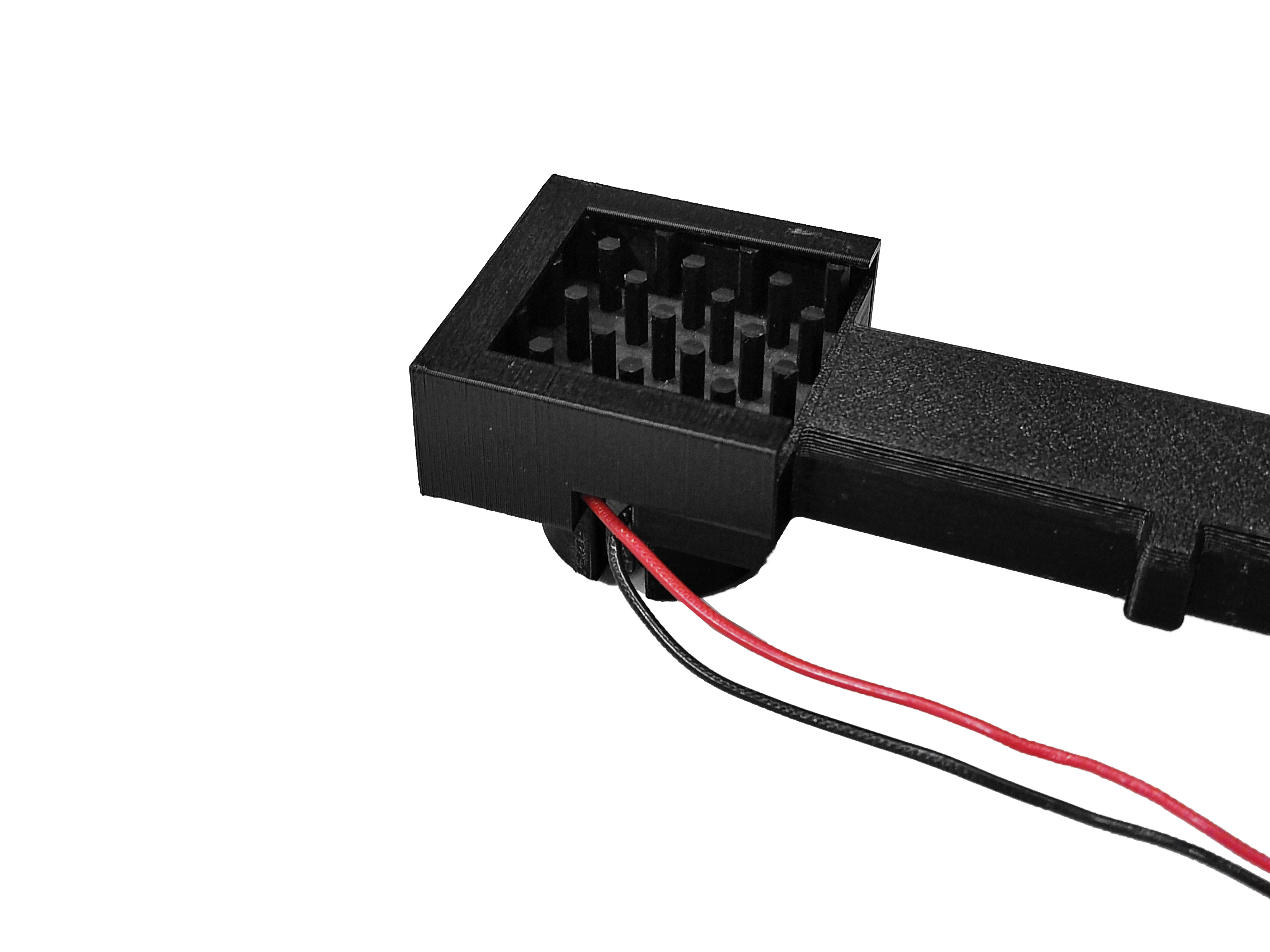
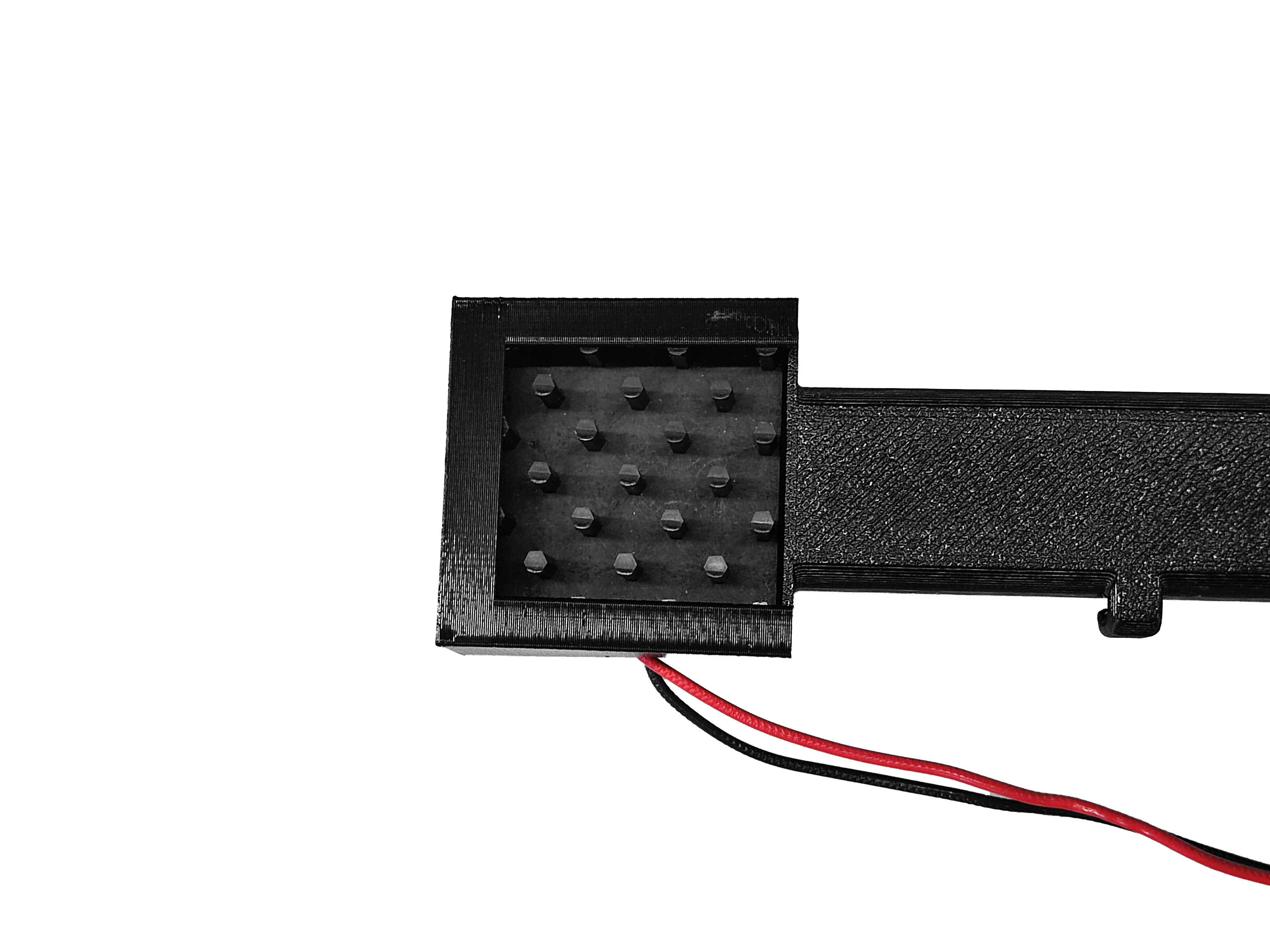
Step 4: Assemble the condenser lens, LED, and heatsink
For this step use Nitrile gloves
- Fasten a high-power LED to a heat sink using a double-sided thermal tape as described in this guide.
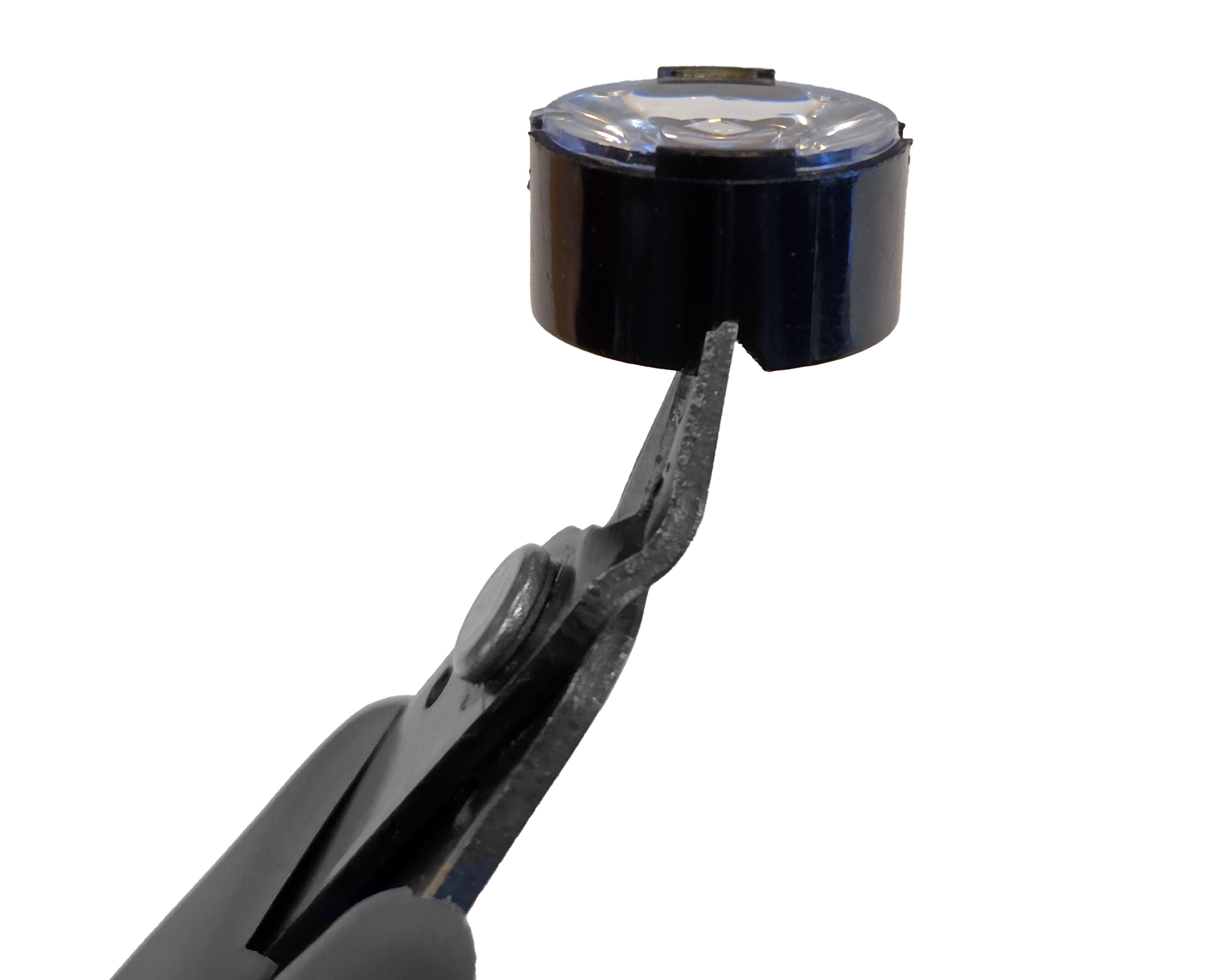
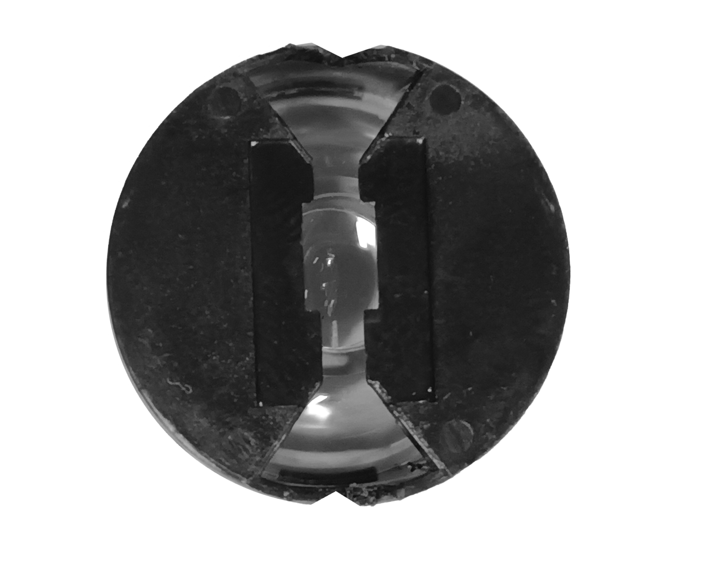
- To fit the cables, make a V cut in the 20 mm circular lens using Precision wire cutter, following the direction of the existing space.
- Fasten the assembly to a 20 mm circular lens using a double-sided self adhesive tape as described in this guide.
- This is the final assembly
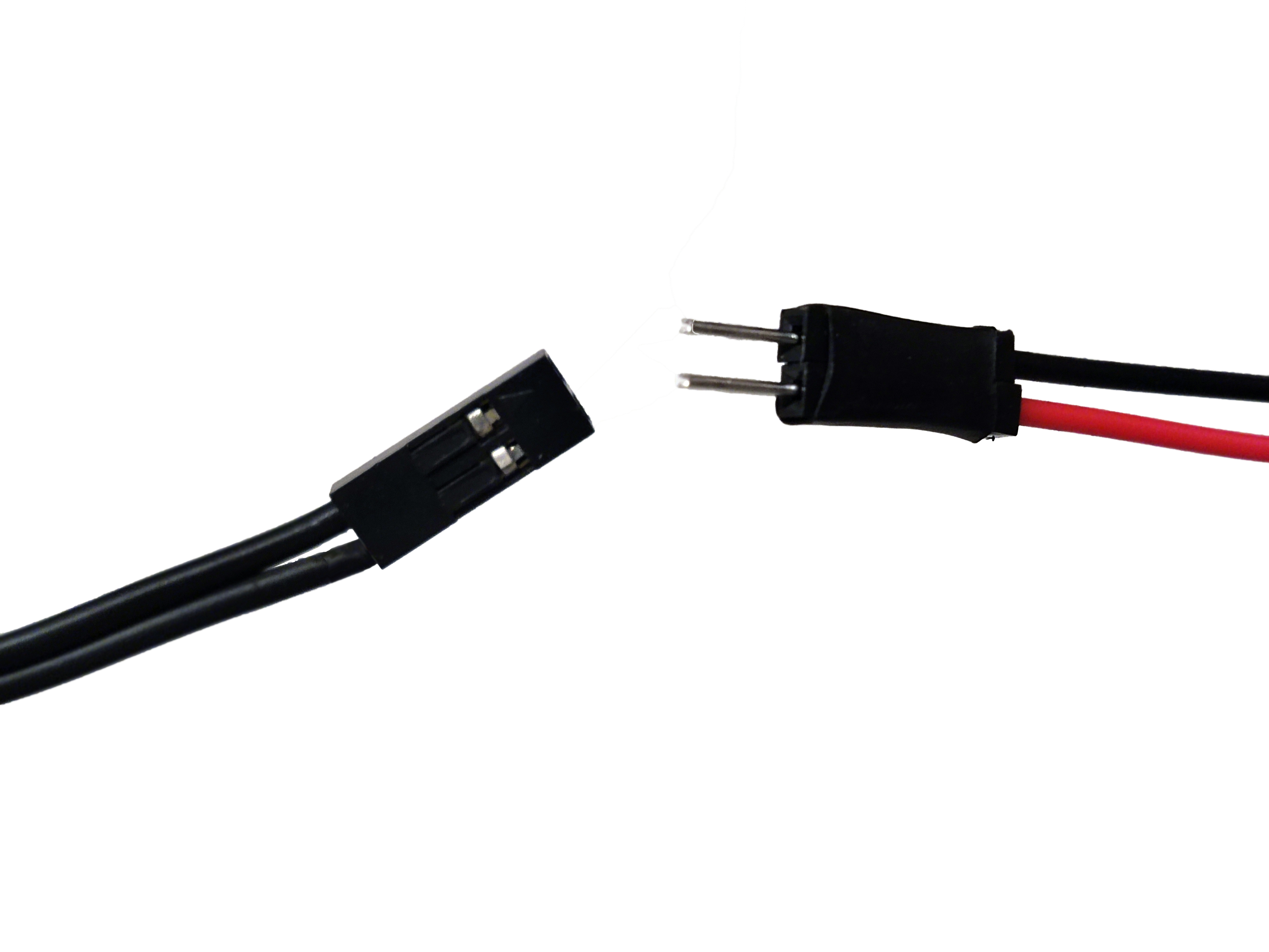
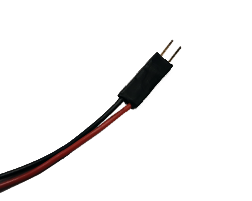
Step 5: Assemble the illumination wiring
- Take the red and black cables of the illumination assembly and crimp them using two male connectors and a crimper as described in this guide.
- Attach a 2 pin Du Pont connector female housing to it.
- This is the illumination wiring
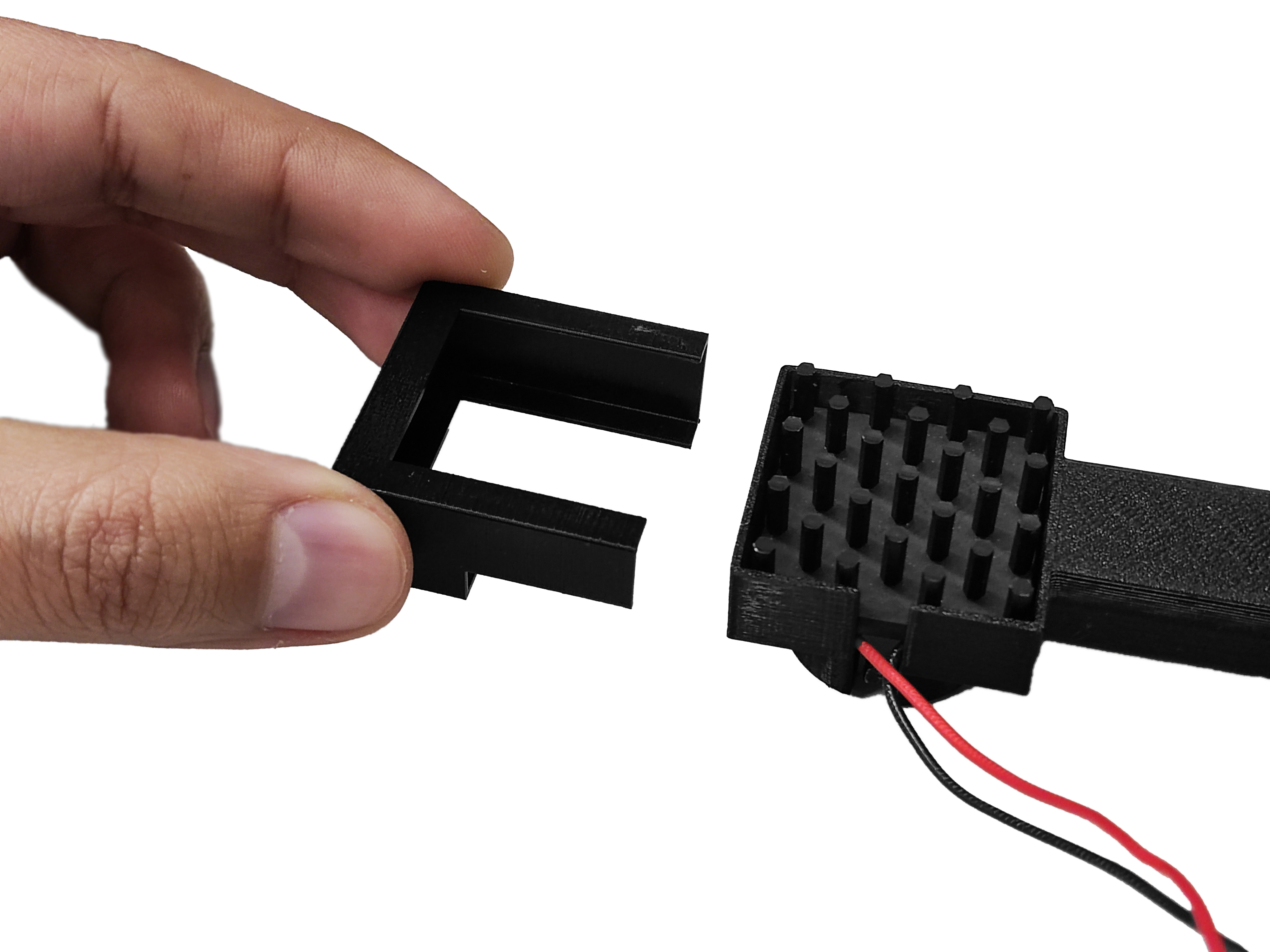
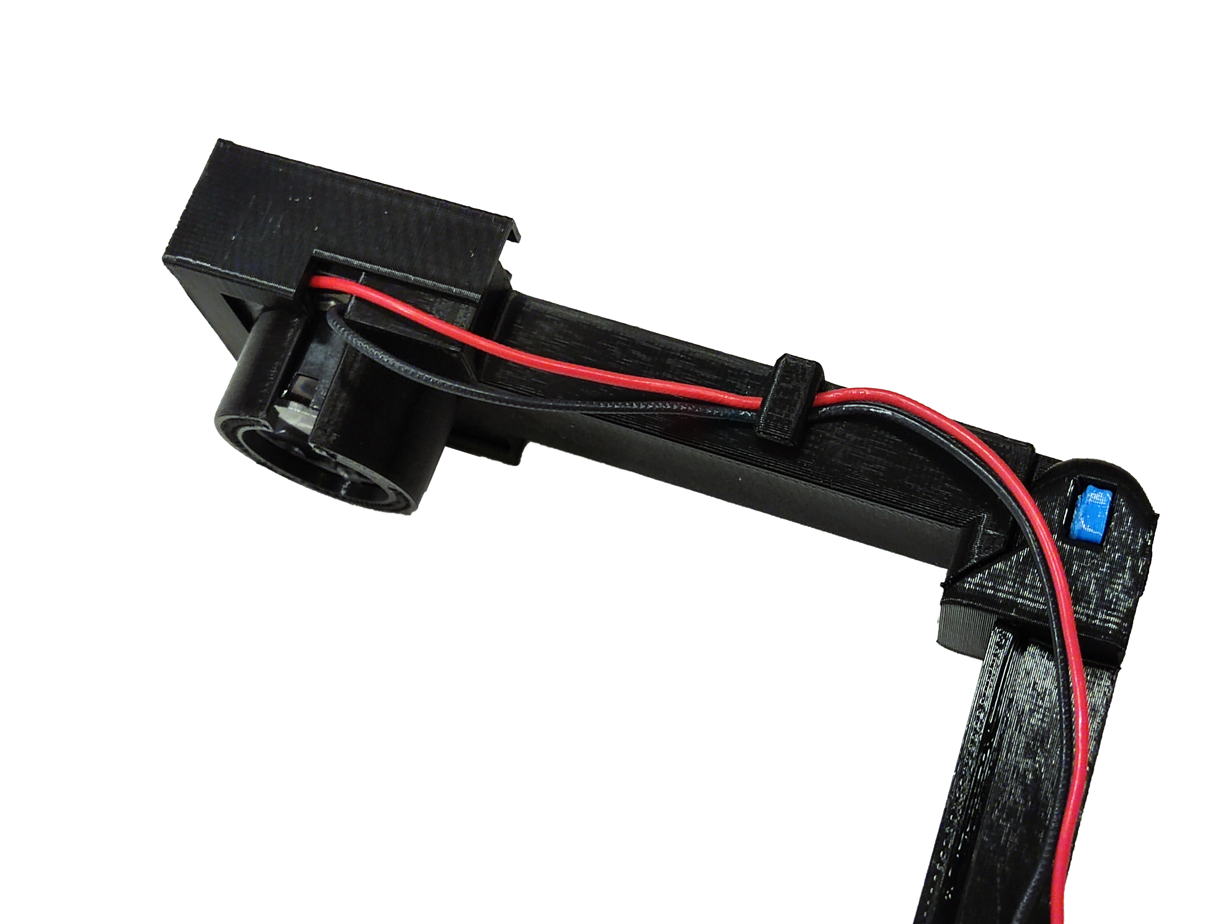
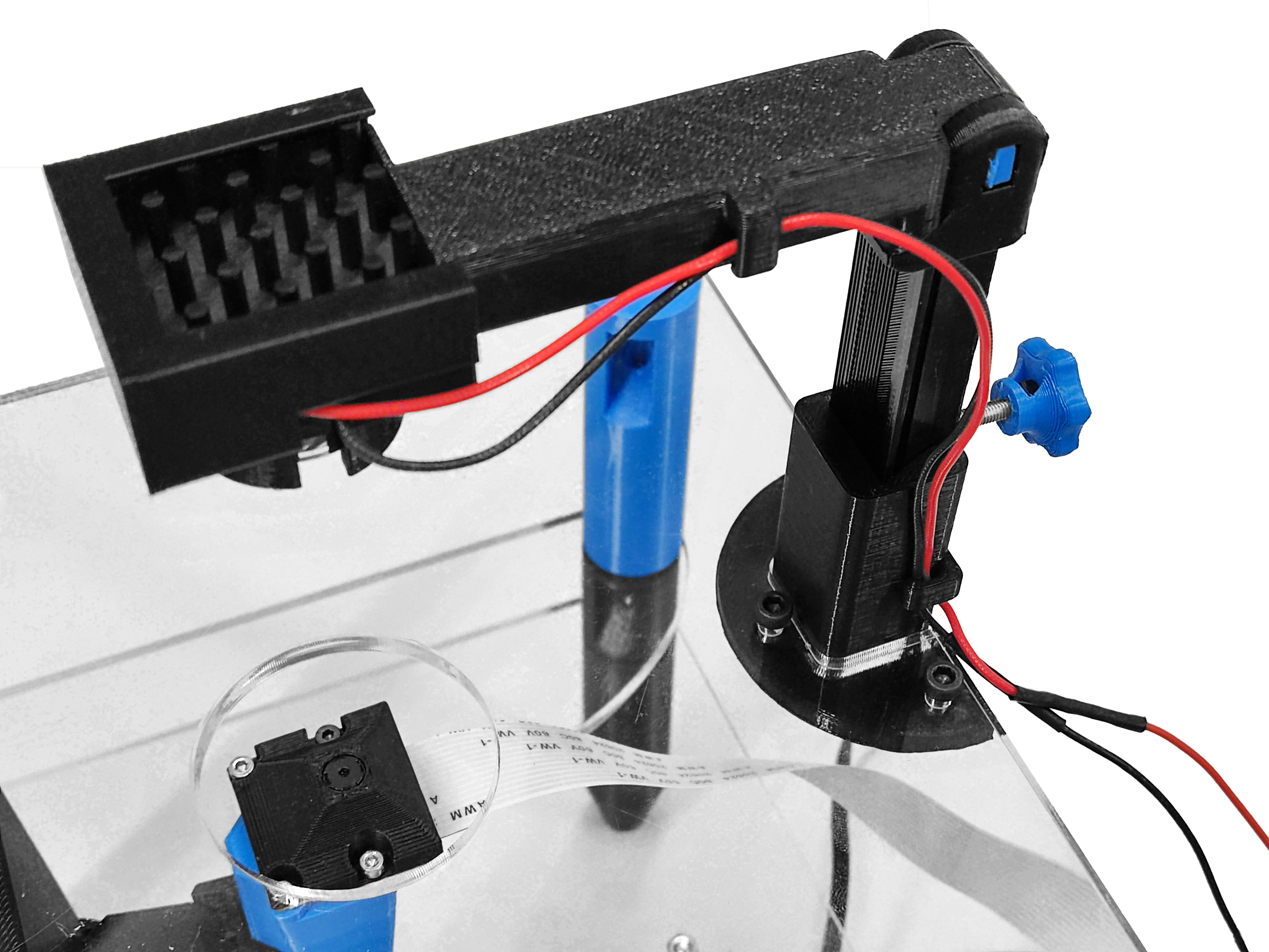
Step 6: Mount the illumination assembly
- Position the illumination assembly in the illumination arm. One side of the LED holder has a space for cables.
- Secure the assembly using a cover.There is also space for cables, use it as reference.
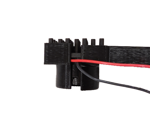
Step 7: Attach the illumination wiring
- Insert the illumination wiring to the cable clip next to LED holder
- Mount the illumination arm assembly to the base
- Insert the illumination wiring to the other cable clip in the base
Step 8: Connect the strobe
- Connect DuPont female 2-pin connector of the strobe cable to the 2-pin male connector of the illumination wiring. Be careful to connect positive and negative terminals in wrong position.